


2D or even 3D CAD software is familiar to the majority of people, with packages like AutoCAD or TurboCAD. being more or less universally known. CAM software on the other hand is not so familiar. The simplest difference is that CAM takes work produced in CAD and uses it as the basis for a real-world manufacturing process. In this instance, a CNC machine.
Numerous CAD and CAM packages are available to the user, from free to painfully expensive. For this tutorial we will focus on QCAD by Ribbonsoft. The software is relatively inexpensive (licenses start at 33EUR) and is available for a resettable trial period. This enables users to get to grips with the basics, and is reasonably easy for a CAD novice to understand. QCAD is also cross-platform compatible available on Windows, Mac or Linux machines, and it includes a basic CAD -> CAM interface adequately servicing our needs.
On opening QCAD the user is presented with a blank document. I am working in Metric, however if you choose to work in Imperial units it is easy to switch between the two units of measurement in the program Preferences. The underlying methods are unchanged of course.

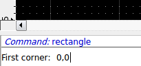
To begin with, we will draw a rectangle with dimensions of 35mm by 45mm. The keyboard shortcut, typing 're' activates the 'Rectangle' command. The cursor will change to a set of yellow crosshairs, indicating a command has been invoked and is active.

The command line at the bottom of the screen indicates that the rectangle command is waiting to for the user to specify the coordinates of the lower-left corner of the rectangle. With the rectangle command still active, click in the command line window where it requests 'First corner:' and type '0,0' (note the comma separating the two zeroes) and press <ENTER>.
To complete the rectangle command we also need to specify the coordinates of the upper-right corner. In the command line window type '35,45' and press <ENTER>. The rectangle is drawn on the screen with the exact dimensions of 35mm x 45mm.

Often when drawing in CAD packages, it is useful to add guidelines to help you work. These are erased when the drawing is complete. In this example it is handy to draw a centreline for our trussrod cover. Click the right mouse button to cancel the Rectangle command or press <ESCAPE>. Same as we did to invoke the 'Rectangle' command, type 'li' to activate the 'Line' command. By moving the yellow cursor near the top edge of the rectangle you will note that the word 'Middle' appears.
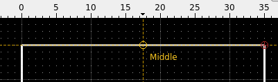
This is an automatic object-oriented snap that allows us to select a key property of items already drawn on the screen with absolute accuracy. Other object-oriented snaps include the centre of a circle, an intersection between two objects or the end of a line, amongst others. In our case we will draw a line from the middle of the top edge to the middle of the bottom edge of the rectangle. Click the middle of the top edge to start drawing the line and click again on the middle of the bottom edge to complete the line. Right-click to stop drawing additional Line segments and right-click again to cancel the Line command.


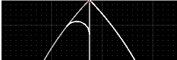
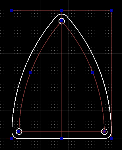
To give the trussrod cover a bit more visual appeal we will curve the sides in a kind of bullet shape. To achieve this we will take advantage of object oriented snaps again. Type 'a2' to start the 'Arc With 2 Points and Angle' command. Using the object oriented snaps click on the top of the centreline to start drawing an arc.

While the end of the arc is 'attached' to the cursor, click in the Angle box at the top of the screen and type '45'. To complete drawing the arc click on the lower-left corner of the rectangle.

The mirror image can be drawn while the Arc command is still active. Left-click the lower-right corner of the rectangle and click again at the top of the centreline.

Note that this time we have gone from bottom to top. This is because the Arc command relies on an anticlockwise rotation when being defined. Clicking top to bottom would generate an arc facing the opposite direction. While this can be reversed so that the arc is drawn clockwise by changing the drawing preferences, it is quicker to remain in anticlockwise notation while the command is still active from the first arc. Right-click to cancel the Arc command.
Now that the trussrod cover is starting to look roughed out, lets refine the shape a little. The three corners of the cover can be rounded over slightly by invoking the 'Round' command. Type 'rn' to start it. In the radius box at the top of the screen type '2.5'.

Left-click one of the two arcs on the trussrod cover near the peak. Note that as you go near each entity it changes colour to grey. Move the cursor near to the other arc. Notice how QCAD offers 'suggestions' as to where the round-over will be if you left-click again.

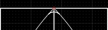
Click when the round-over of the peak becomes one of the suggested options on the screen.

The two remaining bottom corners can also be rounded over using the same process. Right-click to cancel the Round command when finished.

To finish off the cover we'll add some screwholes at each corner. The easiest way to achieve this is to use the existing outline and offset the edges inwards to provide some useful guidelines (we'll delete these once finished). Type 'lp' to invoke the 'Parallel Lines with Distance' command. In the distance box at the top of the screen type '2.5'.
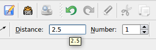
As for the 'Round' command, hover the cursor near each edge of the trussrod cover, and when QCAD's suggested location for the parallel line appears inside the boundary of the cover, click the left mouse button to create the new parallel line.

Repeat for all three edges. Cancel the Parallel Lines command when finished.

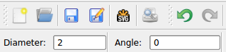
The screwholes are simply circles placed at the intersections of the parallel guideline we just created. Type 'ca' to start the 'Circle With Diameter' function. In the diameter box at the top of the screen type '2'.
Move the mouse over each of the corners of the parallel guidelines and left-click when the object oriented snap 'Intersection' appears. Cancel the Circle command when complete.


All the unwanted guides can now be removed from the screen. To do this simply select all of the unwanted entities in turn while holding the <SHIFT> key to create a multiple selection.
When all have been selected (indicated by the colour changing to brown) press <DELETE>.

So we now have the drawing of the trussrod cover complete, but there is still a little more work to do before we can pass it on to the CNC machine. The main issue we have to resolve is that the diameter of the cutter needs to be compensated for in order to properly cut the outline of the cover. Without any toolpath compensation the cutter will follow the outline of the part and create a profile too small by the radius of the cutter. This is perhaps best illustrated by overlaying a representation of the cutter on top of the trussrod cover.
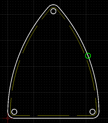
In the above image the green circle represents the diameter of the cutter we want to use on the CNC machine. If the cutter follows the outline of the cover it will create a part that is represented by the yellow dotted line, which is obviously smaller than we want and also encroaches on the screwholes. What we need to do is offset the outline of the cover by a distance equal to the radius of the cutter and have the cutter follow this path instead.
The other issue to be dealt with is the drilling of the screwholes. Again, if no compensation is performed with our basic drawing the CNC machine will simply move the cutter in a circular motion around every screwhole and leave us with oversized holes. What we really want to do is use a cutter with the same diameter as the holes we want to drill and simply plunge the cutter in and out of the centre of each screwhole location.
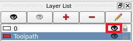
Turning first to the outline path, we need to create a separate drawing layer that contains only the toolpath we want the cutter to follow. To create a new layer click the red '+' button in the Layer List menu box on the right of the screen.

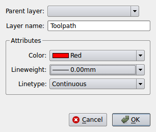
In the popup dialogue give this layer the name 'Toolpath' and change the colour to red. Click OK when done.
Make sure the new Toolpath layer is selected in the Layer List and invoke the Parallel Lines command ('lp'). We will use a 2mm diameter cutter on the CNC machine, so we want the toolpath to be offset from the outer edge of the trussrod cover by the radius of the cutter. Enter 1 in the Distance box. Hover over each of the outline entities and click to create an outside offset. Cancel the 'Parallel Lines' command when done.

The screwholes are easier to deal with. Assuming we continue to use the same 2mm cutter on the CNC machine, this will drill a 2mm diameter hole when plunged in and out of the workpiece. To create a toolpath that only moves the cutter in a vertical drilling action we simply place a Vertex or Point in the centre of each screwhole. Type 'po' to invoke the 'Point' command and using the 'Reference' object snap, click in the centre of each screwhole.

We can now export the drawing as a G-Code file that can be interpreted by the CNC motion control software. Hide the original drawing of the trussrod cover by clicking the 'eye' symbol in the Layer List next to the '0' layer.

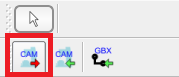
The original white outline disappears from the screen leaving only the red Toolpath layer visible. Click on the 'CAM Export' button on the toolbar to bring up the CAM Configuration dialogue box.
Select the 'LinuxCNC' configuration from the dropdown menu and set the other options as shown below.
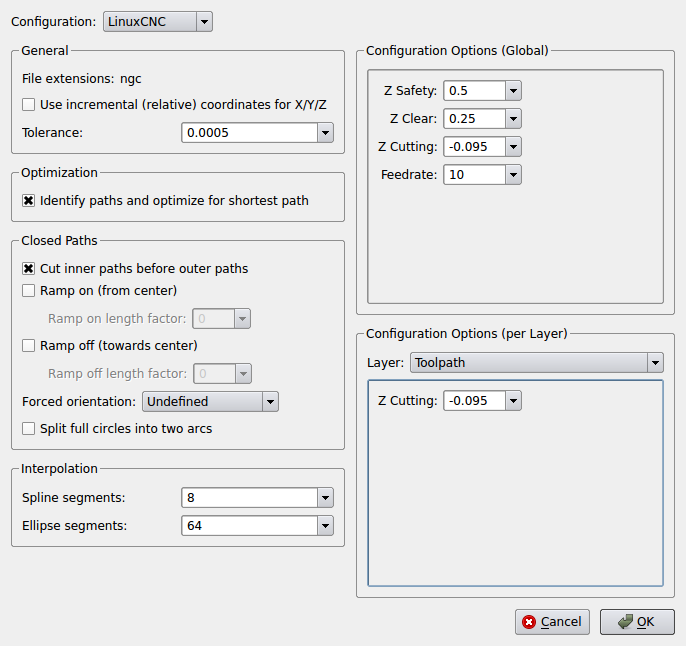
The important settings to take note of are:
- Cut inner paths before outer paths - the order that the CNC machine cuts the object from the material can be important. For this reason we want to drill the screwholes before the outline is cut out. If the outline were cut first there is a risk that the part may move as it becomes free of the surrounding material, rendering the drilling of the screwholes innacurate.
- Z Safety - the distance the CNC machine raises the cutter by to a safe amount from the workpiece to allow for the machine to be started and stopped.
- Z Clear - the distance the CNC machine will raise the cutter above the workpiece when rapidly jogging between different areas of the workpiece.
- Z Cutting - the distance the CNC machine will plunge into the workpiece when performing a cut. As we are wanting to cut the full thickness of the trussrod cover material and drill all the way through for the screwholes, this depth should equal the thickness of the material we are attaching to the cutting bed. In our case we are using some black plastic pickguard material 0.095" thick.
- Feedrate - The speed at which the CNC machine will move the tool when cutting through the workpiece.
In all the above cases the units are expressed in inches or inches per minute. Once all parameters have been set click 'OK', specify a file name and select a convenient location on the computer to save the G-Code to.
Start LinuxCNC and open the G-Code file for the trussrod cover.
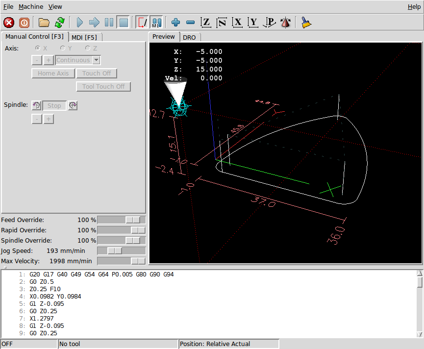
You will notice that the program is drawn such that all cuts are made in one pass at the full depth of 0.095". Doing such a heavy cutting manoeuvre with the tiny bits that the CNC machine uses is likely to destroy the cutting tool. The forces involved are too great for a small machine and such fine cutters. While the three screwholes are fine to be cut to full depth in one go, the outline is not and would be better performed if the cut was made in several passes. Fortunately this can be achieved with some minor tweaking of the G-Code file within LinuxCNC.
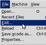
Different modifications or approaches can be used to achieve the same end result. For the purposes of simplicity, we'll use the easiest approach. With the truss rod cover G-Code file loaded in Axis click File -> Edit...
A text editor window opens with the G-Code loaded. The section of code that details the outline cut is highlighted below, beginning with the G1 plunge to Z-0.095 at line 14 and ending with G3 X0.0982 Y-0.0394 I0.1378 J-0.0026 at line 20.

By repeating this section of code several times over and incrementally plunging a little deeper each time we can complete the cut in several passes without stressing the cutting tool. The easiest way to achieve this is to simply copy this block of G-Code several times over and increment the initial Z depth a little during each pass until the final depth is achieved.

With the above code modified as shown click the 'Save' button in the text editor. Return to Axis and click the 'Reload' button or press <CTRL-R>.
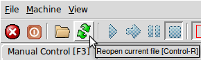
The G-Code is reloaded into Axis, but notice that the truss rod cover outline now contains three identical tool paths stacked on top of each other.

Leave the CNC machine switched off at this stage, home all three axes and run the G-Code. By running the code with the machine switched off it is possible to see a simulation of what will be cut before committing the cutting tool to the material. As the program runs note that the outline cut is made in several progressive layers; each time the tool passes the start of the outline at the lower-left corner it plunges to the next depth and continues around again until the final, lowest outline is completed.

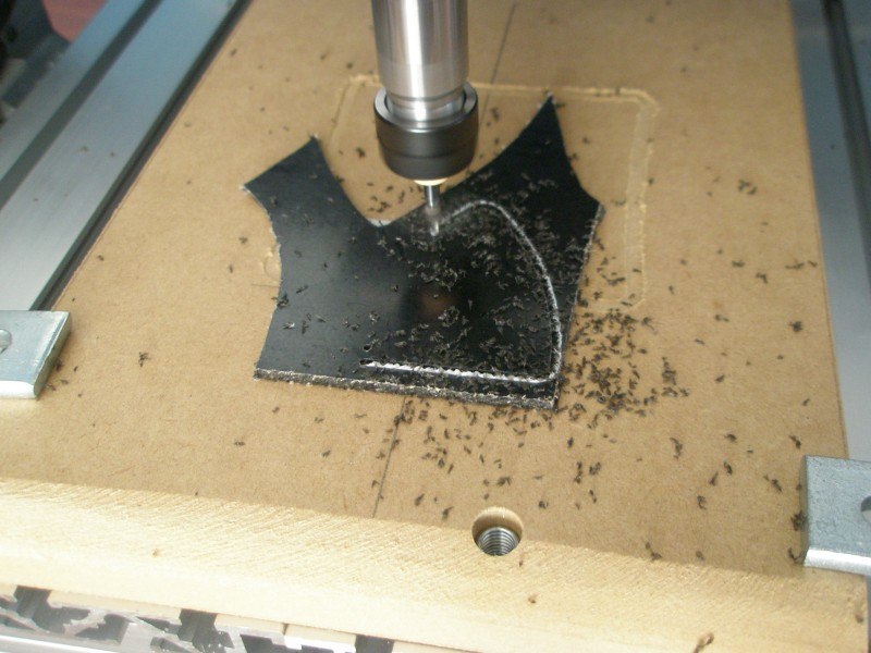
If the simulation appears OK turn the CNC machine on, fit a fresh piece of material to the cutting bed (double-sided sticky tape is sufficient for such a small piece), install a 2mm diameter cutter to the collet, home and touch-off the tool and run the G-Code again. In a couple of minutes you should have a perfectly formed truss rod cover ready to be fitted to an instrument.

----------
Over the course of this four-part series we have demonstrated how the compact CNC machine can open up a whole new world of possibilities in guitar construction. While we have created a rudimetary truss rod cover from scratch, we have barely scratched the surface of what the CNC machine can achieve - from carving out custom pickup rings, creating workshop tools and aids to assist with instrument building and setting up, to engraving and carving intricate designs onto headstocks and fretboards. For a modest outlay of money it is possible to have a device in the workshop capable of precision that, up until the last 15 years, was the domain of the largest manufacturing firms. After mastering basics such as those described above, experimenting with more complex ideas and demanding designs quickly allows a small CNC to transform your working procedures.
There are no comments to display.
Join the conversation
You can post now and register later. If you have an account, sign in now to post with your account.