

Recently I made the decision to step into the world of CNC routing machines and augment my small workshop and tool collection with a modestly-sized unit. With the rise in quality of low-end Chinese-made machines in recent years it has become easier than ever to purchase a small CNC router for home use capable of high precision. A quick search on online auction sites will reveal a vast array of pre-assembled units for sale starting in price from less than $700, with cutting beds up to 600mm x 900mm in size. While I am still a novice at CNC, hopefully my experiences can help others decide if taking the plunge is for them too.
So, why choose a small CNC router? There were several reasons why I personally decided to purchase a desktop machine with the intention of applying it to guitar work:
- I had a limited budget and a small area where I could set up such a machine. A CNC router capable of directly milling a guitar body from a timber blank is physically large, noisy and expensive;
- I was after a way to improve the appearance of my builds by including professional-looking headstock logos and markings, and had thus far been dissatisfied with many of the solutions that utilised decals or transfers;
- I wanted a quicker and safer way to create templates for routing smaller shapes and components used in guitar construction (eg, pickup cavities, headstock outlines, truss rod covers);
- Having decided to explore multi-scale instruments I needed a way to make accurate drilling templates for the individual bridge assemblies commonly used for these instruments;
- Despite wanting to automate some of the construction process, I still wanted to retain the hands-on nature of building an instrument rather than transfer the bulk of the cutting and shaping work directly to a machine;
- The increased accuracy afforded by the machine for particular tasks was attractive (eg, scribing fret slots directly onto a fretboard blank, creating perfectly-fitted control cavity covers).

The CNC machine I eventually settled on was at the smaller end of the scale; a 3-axis desktop unit with a similar footprint to a mid-sized inkjet printer, having a cutting bed of 200mm by 300mm (X- and Y-axis respectively) and a vertical travel of 50mm (Z-axis). The spindle is rated at 200W, with a 1/8” collet which allows the changing of cutters using a wrench system similar to that used on many handheld routers. The build quality of the frame and gantry seems quite acceptable, although for the price paid I would expect some shortfalls in terms of frame flex and milling accuracy of the spindle due to runout and eccentricity. However if you don’t work the CNC router too hard any errors in the finished milling process will be minimal, and achieving sub-micron precision in a material such as timber is probably a moot point anyway.

A separate controller interface unit is supplied featuring variable spindle speed via a dial on the front panel and PC connectivity through a parallel port on the back. It is worth noting that most of the models which utilise a parallel port to interface with the computer require a desktop PC rather than a laptop, as the battery power management features of the latter are not conducive to reliable operation of the CNC router. Commonly available USB-to-Parallel Port adaptor cables are also incompatible with these units. However, if your host computer does not have a built-in parallel port you can purchase and install an aftermarket PCI parallel port card, which is exactly the path I chose.

The unit also came equipped with a selection of endmills, a set of rudimentary work piece holding clamps, a number of allen wrenches and spanners and an evaluation copy of the Mach3 CNC motion control software. While the supplied endmills are satisfactory for learning the ropes and experimenting with different cutting operations, you may wish to invest in a small collection of higher quality endmills, which afford a far superior finish and longer working life than the factory-supplied ones. The controller is connected to the CNC mill via several cables with locking collars to prevent them inadvertently working loose. An unexpected bonus feature of the particular model I chose was that the controller circuit board is fitted with several unpopulated connectors that allow the retro-fitting of axis limit switches. On more fully-featured units these limit switches are fitted to the moving components as a safety measure to prevent the software accidentally driving the CNC machine past its maximum limits of travel, or to allow automatic homing of the cutting head (more in this in future articles).
On the subject of software, there are two main options for driving a parallel port-based CNC router; the above-mentioned Mach Series software which is for Windows-based machines and LinuxCNC (formerly known as EMC2) for Linux-based systems. As LinuxCNC is a well-supported open-source option for these machines I elected to take this option and install a Linux partition on my host computer. Conveniently, LinuxCNC offer several LiveCD versions of their software, which has the motion control software pre-installed on a Linux operating system. The operating system can be run directly from CDROM or DVD without having to be installed on the PC. If the user decides that they would like to continue using Linux, they can choose to install the operating system and motion control software directly from the LiveCD.
As these machines are directly exported from China or imported via an agent, technical support tends to be quite limited. The units require some software configuration in order to move the axes in the correct direction at the correct rate. The machine itself is incapable of knowing where it is positioned relative to the cutting bed, or how many turns of the axis motors are required to move it an exact distance without some form of calibration data maintained by the host software. Fortunately there are several online resources to help users configure their CNC routers in order to achieve precise operation.
Once configured to run from the motion control software, the user can load files into the application to direct the cutting head to manoeuvre around the work piece at pre-determined directions, speeds and depths in order to create the final object. The language used in these files is known as G-Code and consists of text entries directing the axis motors to move in a specific direction at a certain rate. Other specialised commands in G-Code are used to command the spindle motor to turn on and off, make the program pause at key steps in the routine, or cause the axes to move in predefined ways such as cutting an arc or drilling a hole.
While it is possible to create a G-Code file from scratch by typing commands one at a time in a text editor, it is far easier and quicker to use a Computer Aided Drafting or Computer Aided Machining (CAD/CAM) application to draw the intended cutting paths and convert the subsequent drawing to its component G-Code commands. The user has the ability to quickly mock up an outline of, say a pickup routing template, export the resultant drawing as a G-Code file, open the file in the motion control package and cut out the routing template from a sheet of MDF with sub-millimetre accuracy in a few minutes.
While some CAD and CAM applications are integrated into one common application, there are also many offered as separate software solutions. Some packages are open-source and free while others cost anywhere from a few tens of dollars to well in excess of $1000, all with varying levels of ease of use, feature sets and functional integration.
Below are a few examples of what operations are possible using the small desktop CNC machine when applied to guitar building.
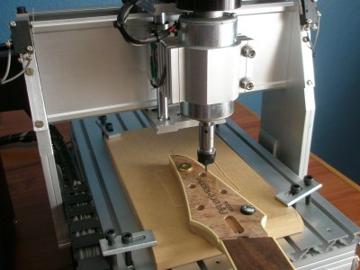
This headstock logo was first engraved while being held in a simple jig to allow the workpiece to be accurately positioned without moving. The work was done in two passes, with the larger of the two pieces of text milled using a 0.8mm diameter endmill, and switching to a 0.7mm endmill for the smaller text. The resultant cavities were filled with black-tinted epoxy and sanded flush:


Cavity covers can be directly cut on the CNC router from thin timber stock, including drilling the screw holes in one pass. To create a matching routing template for recessing the cover into a body it is a trivial matter to take the original cavity outline and scale it in CAD. The resultant file will create a perfectly fitting routing template for that cover. As I was unsure if the machine would struggle to mill such a thick piece of perspex, I milled a 'master' template from 6mm MDF and then used a handheld router fitted with a pattern-following bit to transfer the MDF template to the perspex sheet:


If your router has a bushing guide or pattern-following plate attachment you can use it in combination with a small diameter bit to cut cavities with tighter radius corners than woud be possible using a typical 1/2" template bit with integrated bearing. The problem with using a bushing guide is that the template used must be created oversize by the radius of the bushing minus the radius of the cutter. Creating such a template in CAD and then milling it on the CNC router is simple. In the following example I have created a routing template to suit the bushing guide for my router. The cutter used was a 1/4" straight bit and the bushing guide is 16mm in diameter, so the template has been created with a consistent (8mm - 3.175mm) 4.825mm offset to achieve the intended cutting profile for a humbucking pickup cavity:


Accurately positioning the independent saddles used on multi-scale instruments can be tricky, as the risk of misalignment is increased compared to a one-piece bridge. Determining the angle of the saddles for the differing scale lengths can be problematic, and if you are constructing instruments where the scale lengths used differ from build to build, making a drilling jig by hand is time consuming. This drilling template was milled and engraved into 1/8" perspex in about 15 minutes and includes the mounting holes for the saddles, the through-body holes at the rear of each saddle, a centreline to assist in positioning the template on the body and the intonation reference mark for the scale lengths used:

The CNC machine can also be used to create simple tools for use in building and setting up instruments. The time taken to create this four-sided radius gauge was about half an hour, from mocking up the basic shape in CAD to removing the perspex sheet from the machine's cutting bed. If the tool was to get lost or damaged, creating a replacement should only take a few minutes:

Pros:
- A ready-to-go solution out of the box with minimal assembly required
- Competitively priced with good accuracy and construction quality
- Excellent finish achievable on the object being machined
- Capable of machining a wide range of raw materials (MDF, plywood, timber, plastic, soft aluminium)
- Good support from open-sourced software solutions
- Small footprint for installations where space is at a premium
Cons:
- Generally not suitable for direct cutting/shaping of the major components used in guitar construction (eg, cutting body outlines, neck profiles, cavity routing) or machining harder materials (eg, making custom metal components for bridges)
- Minimal after-sales technical support
- The control interfaces supplied with the smaller and cheaper units usually require a desktop PC fitted with an archaic parallel port.
- The software used can be challenging to get to grips with if you’re not familiar with Computer Aided Drafting principles and terminology.
- Hidden costs associated with using a CNC – purchasing good quality cutters and CAD/CAM software for example
----------
In future articles I will explore calibrating the desktop CNC router and covering some of the basic operations of the associated CAD, CAM and motion control software packages.
Edited by curtisa
-
 3
3

Join the conversation
You can post now and register later. If you have an account, sign in now to post with your account.