


So you’ve decided to launch yourself into the world of CNC machining. You’ve done some research and lurked around many online forums and resources looking for information regarding which model to choose and what features the unit needs. You’ve plonked down your hard earned cash and a big cardboard box has arrived in the mail containing a bright, shiny new CNC router. It’s been assembled and set up on your desk. Now what?
Fundamentally, most basic CNCs will have a bed which workpieces are secured onto and a overhead gantry that travels the length of the table. Onto this gantry a secondary carriage travels over the width of table. The spindle itself is attached to this carriage and can move vertically. The spindle rotates a cutting tool at high speed to remove material from the workpiece. The three movement directions (side-to-side across the table, up and down the length of the table, vertically up and down perpendicular to the table) are the three axes of motion that the machine can operate in; X, Y and Z respectively.

Each axis is independently controlled by specialised motors known as steppers, which are designed to rotate either direction by precisely known amounts. The rotation of these motors is translated into simple linear movement (backwards and forwards). Commonly, threaded rods ("lead screws") pulleys or toothed belts are used for this purpose. Larger machines can sometimes use these in combination (such as pulleys for X and Y, leadscrew for Z). Each have their respective advantages and disadvantages in accuracy, cost, speed, load capacity, etc. Lead screws are most common in small CNCs for all three axes.
The precise rotation of the stepper motors is controlled through the application of electrical pulses. By co-ordinating the number, length and frequency of the electrical pulses, the CNC machine can be made to execute precise synchronous motions to move the cutting tool around the workpiece in complex paths.
The generation of these control pulses is performed either by dedicated standalone control consoles or by software on a common computer. Non-production level CNC tends to utilise the second option; the steppers driven by a simple external interface unit that sits between the machine and PC which handles the translation of the software stepper signals into the heavier-duty control signals that drive the motors.
Software generation requires that a motion control application be installed on the host computer. Two of the most popular motion control solutions at the moment are Mach3 or Mach4 (for Windows based computers) and LinuxCNC for (Linux-based operating systems). In this article we will use LinuxCNC to illustrate how to set up the desktop CNC router; fundamentally the operating principles are similar between the Mach-series software and LinuxCNC.
Both options require the host computer to have a parallel port for communicating with the control interface. Laptops and USB-to-parallel adaptors are not recommended for software stepper pulse generation. The main advantage of favouring the "old" parallel port standard is that many signals can be sent simultaneously; despite being far faster, USB is purely serial and asynchronous; one piece of information at a time and "arrives when it arrives". Parallel is far closer to being a real-time interface, which USB to parallel adaptors do not reliably replicate. PCI parallel port cards on the other hand are a satisfactory option if your host computer doesn't feature a parallel port.
Installation of a Linux operating system and the LinuxCNC application is beyond the scope of this article, however it is extremely simple; LinuxCNC is available as a LiveCD installation, whereby the user has the ability to boot a pre-compiled version of LinuxCNC from a CD, DVD or USB memory stick without installing the operating system onto the computer. This operating system image is available to be downloaded from the LinuxCNC website. A permanent installation of Linux and LinuxCNC can be performed from the LiveCD if the user so chooses at a later date.
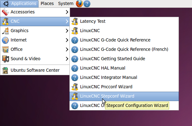
The first requirement in setting up the CNC machine is to create a configuration file. This contains the specifications of the CNC motors so that they are driven at the correct speed/rate, acceleration, direction, etc. From the menu bar Click ‘Applications’, navigate to ‘CNC’ and select ‘LinuxCNC StepConf Wizard’.
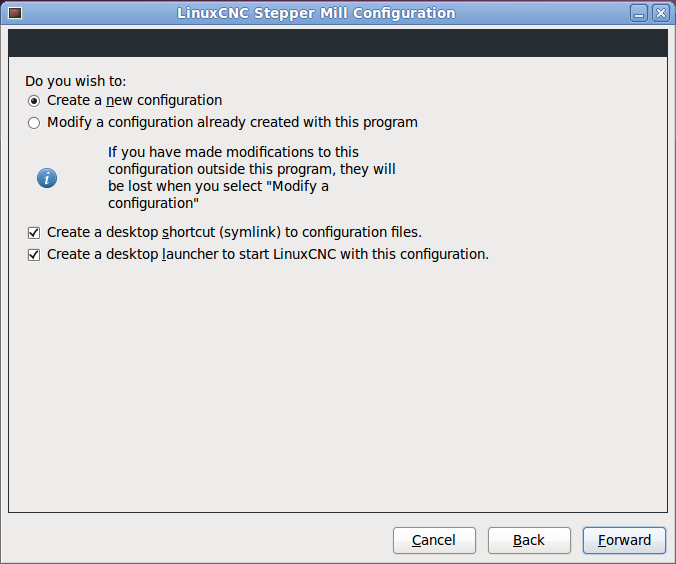
If this is the first time that StepConf Wizard has been run a new configuration must be made. The user also has the option of opening an existing configuration to either adjust existing settings in their recently created configuration, or use another configuration as the basis for their new CNC router. In this case we will create a new configuration from scratch. Click ‘Forward’ to move to the next page in the StepConf Wizard.
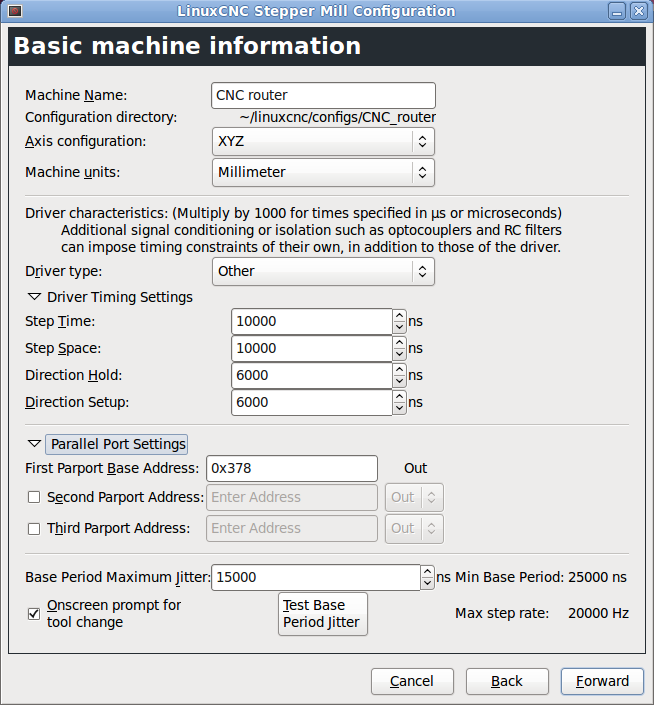
In the next screen the configuration can be given a meaningful name and basic setup parameters defined, such as units of operation (millimetres or inches), how many axes the machine operates with (in our case three axes – XYZ), parallel port addresses and driver signal timing. If your CNC machine comes with data or a user manual then use this to set the driver timing settings. If there is no data supplied you may have to search online to find some information regarding the suggested timing parameters, or experiment to find the best trade-off for reliable operation of the CNC router.
- Step Time and Step Space - the width of the electrical pulse applied to each stepper motor and the subsequent gap between each successive pulse, expressed in nanoseconds. Too small a step pulse or space and the motor will miss a step. Too long and the CNC axis movement can become unacceptably slow.
- Direction Hold and Direction Setup - In addition to the step pulses themselves, secondary signals are generated by the motion control software that change the order of the pulses being applied to the steppers. Changing the order of the pulses changes the rotation of the motors from clockwise to anti-clockwise. The "Direction Hold" and "Setup" parameters define the amount of time the direction signal applied to a stepper motor needs to remain activated after a step pulse has been issued, and the amount of time the direction signal needs to be applied to the stepper before issuing the next step pulse. Too small a direction hold or setup and the motor can miss a change in direction and overshoot its intended stop point. Too long and the CNC axis movement can become unacceptably slow.
In most cases the values shown will work as-is and require no further adjusting.
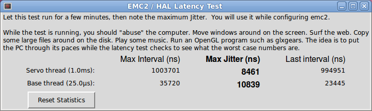
The last key item that requires attention on this page is the ‘Base Period Maximum Jitter’ setting. Instructions to the CNC (via the interface) are generated by software, so there is a potential that something occurring in the computer or operating system outside the control of the CNC machining application may interrupt the continuous supply of timely instructions (eg. graphics redrawing on the screen, hard drives being accessed, etc). Consequently we need to ensure that any interruptions that do occur do not interfere with the normal operation of the CNC machine. To find out what this minimum safety net should be the StepConf Wizard includes a ‘Jitter Base Period Test’ function. After running the test for a few minutes this returns a suitable ‘Base Period Maximum Jitter’ value. This states how much the system might be expected to be delayed during normal operation; the configuration then makes sufficient allowance to avoid interruptions in the generation of the stepper control signals. Click ‘Forward’ when all fields have been filled in.

Leave the Advanced Configuration Options unchecked at this stage and click ‘Forward’ again.
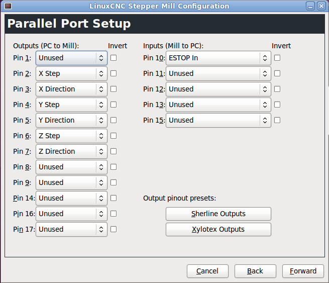
The Parallel Port Setup screen is where we define what each pin of the parallel port on the computer is expected to do when connected to the CNC machine. Again, consult any data or the manual supplied with the CNC router to determine how each pin is to be connected. As we are configuring a basic 3-axis machine the minimum required pins to be configured will be X Step, X Direction, Y Step, Y Direction, Z Step and Z Direction. The other important pin to configure is the Emergency Stop (or E-Stop) input from the machine. Nearly all CNC machines will be fitted with a large E-Stop switch that the user can hit in the event that the machine begins executing some unintended moves, and signals the motion control software to unconditionally stop moving the axes.

The next three screens are used to configure the behaviour of each stepper motor; their speed, acceleration and limits of travel. Each axis is configured independently but the options presented are identical:
- Motor Steps Per Revolution – how many steps the motor needs to perform to complete one full rotation of the shaft. Manufacturers of stepper motors often express this value as degrees per step. If your stepper motor has this value specified as 1.8 degrees per step then Motor Steps Per Revolution is equal to 360 degrees divided by the degrees-per-step value, or 360/1.8 = 200.
- Driver Microstepping – the resolution of a stepper motor can often be increased by the action of microstepping. The basic degrees-per-step specification of the motor is enhanced by the driver forcing the motor to make an intermediate ‘soft’ step in between each 1.8 degree ‘hard’ step. In the same way that a picture with higher resolution can display more detail on a computer screen, a stepper motor with more resolution can perform finer movements. The trade-off is that the more microstepping you add the less torque that motor is able to generate. In practice a microstepping value of either 2 or 4 is a good compromise. Note that if you set microstepping to 2 it will require that Motor Steps Per Revolution be increased to 400 to maintain the relationship of the number of steps to complete one revolution of the motor shaft. Setting microstepping to 4 will require Motor Steps Per Revolution to be set to 800.
- Pulley Teeth – only required for CNC machines that use pulley systems to drive the axis. This is where you would specify the gearing ratio of the pulleys. We are using a lead screw in the desktop CNC machine so leave these two fields set to 1.
- Leadscrew Pitch – the pitch determines how far each axis will travel when the lead screw is rotated one full revolution, and its setting is critical to ensure that the axis travels the correct distance when commanded to do so. If the units of operation specified earlier were inches then the lead screw pitch is expressed as threads per inch. If millimetres were specified then this value is expressed as millimetres per revolution. Consult your CNC machine datasheet for information on the specifications of lead screw fitted. As an alternative most lead screw pitches can be measured reasonably accurately by using a ruler to count the number of thread ‘peaks’ within one inch, or the distance in millimetres between two successive thread peaks.
- Maximum Velocity and Maximum Acceleration – sets the maximum speed and acceleration of the axis before the CNC machine starts missing steps or losing accuracy when changing directions. As no real life object can accelerate from a standstill to full speed instantaneously, we need to specify a value in the ‘Max Acceleration’ field to limit how quickly the CNC motion control software tries to make the machine change its speed when either accelerating from zero, coming to a stop at the end of a manoeuvre, or changing directions suddenly when transitioning between two trajectories. In general this is set by experimentation with your particular machine, but the values presented here should work with the smaller desktop CNC routers as a starting point.
- Home Location – the default location the axis will set itself to when the machine is told to ‘return home’. The home location can actually be anywhere you like within the axis limits of travel, but is typically set at 0 (which would equate to the lower-left corner of the table with the Z axis at maximum height). Every time the software is started up the physical location of the CNC machine is undefined. Until the CNC machine is homed it cannot know where its limits of travel are (below) and therefore cannot commence a machining job.
- Table Travel – specifies the ‘soft’ limits of motion that the axis can move within, and is expressed as either millimetres or inches depending on how the units of operation were set earlier. For each axis this is typically set to the maximum travel that the axis can move to before reaching the end stops. When the motion control software detects that the axis has reached its soft limit it will not attempt to drive the CNC router beyond this value. Note that when setting the Z axis the Table Travel fields are normally set as a negative number to zero, rather than as zero to a positive number. The convention here is that the Z axis moves negatively with respect to the surface it is bearing down upon.

The last option for each axis is the ‘Test this Axis’ function. Clicking on this will bring up a window that allows the user to see if the configuration created thus far is appropriate for their machine. With the CNC router connected to the computer and powered up the axis under test can be manually moved using the two ‘Jog’ arrow buttons, or the axis can be set to automatically swing back and forth by a set amount according to the ‘Test Area’ fields. This is useful for determining if the axis is moving by the correct amount based on the ‘Motor Steps Per Revolution’ and ‘Lead screw Pitch’ settings, and also if the ‘Max Velocity’ or ‘Acceleration’ settings are going to result in missed motor steps. Assuming that step direction was set up correctly earlier under the ‘Parallel Port Setup’ window for each axis, clicking the right ‘Jog’ arrow should make the X axis move towards the right of the table, the Y axis move away from the front of the table and the Z axis move vertically upwards.

Clicking ‘Forward’ after configuring the last axis and then ‘Apply’ will create an icon on the desktop allowing the user to launch the motion control software using the created configuration file.

And that’s it! If you’ve made it this far you’ve successfully created a configuration file to suit your CNC router. By double-clicking the 'launch CNC-router' icon on the desktop, the configuration file will pre-load all the necessary parameters for the CNC machine and start up the motion control software.
----------
In the next article we will begin creating a basic G-Code file to run the CNC router with. In doing so we will also verify that the machine operates correctly, and the axis motion is correctly scaled to create 1:1 cuts in preparation for applying the CNC machine's abilities to creating luthiery-related components.
Edited by curtisa
-
 4
4

There are no comments to display.
Join the conversation
You can post now and register later. If you have an account, sign in now to post with your account.