


Mender
-
Posts
331 -
Joined
-
Last visited
-
Days Won
1
Content Type
Profiles
News and Information
Tutorials
Product Reviews
Supplier Listings
Articles
Guitar Of The Month
Links and Resources
Forums
Gallery
Downloads
Posts posted by Mender
-
-
That is pretty smucking fart

-
-
Some beautiful guitars again this month, and I debated long and hard between two of them, with Pan_kara's being one of them, but in the end I voted for psikoT's ash/wenge 7 string. The carve with the black on top just looks so perfect

-
 2
2
-
-
Those two methods of doing the tone control are functionally identical, and assuming the rest of the wiring is done correctly, neither method would cause the volume to be on full all the time. You need to check your wiring very carefully.
-
I have to agree with the majority here. I can't see enough features of 'Evil' to judge it properly, although the face looks beautiful. While I'm not an Explorer type guitar lover, I am voting for 'Blackhawk', mainly because I can see much more of the workmanship that has gone into it.
-
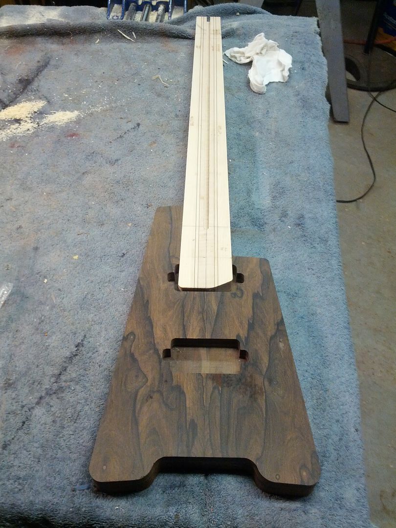
That is a similar idea to the Stewmac guitar holder http://www.stewmac.com/shop/Finishing_supplies/Equipment:_Spray_equipment/Freehand_Holder.html?actn=100101&xst=3&xsr=269925
-
Three entries similar in design. Hmmm, after much deliberation, sdshirtman has managed to steal my vote

-
That is exactly how the Stewmac pots work, and all other blend pots I've ever seen. Track 1 is 500k between centre and left, and short circuit between centre and right. Track 2 is the opposite way round.
If the resistance was 500k evenly spread over the full range of movement end to end, then the centre detent position would be 250k from each end, giving only half volume on each pickup.
Interesting. I opened up my Yamaha bass to verify the blend pot against what you've said, and it's fitted with a dual log/anti-log pot (mid point is 75% of full travel on each element). Horses for courses...
The Stewmac ones are linear, as are the two I have here, and each track definitely measures (within 5% tolerence) 500k from one end to centre. From the centre to the other end is virtually a dead short, no more than about 15 ohms.
-
...I just need to be sure as what I'm really looking for is a blend pot that goes from 500K for the first signal and 0 on the second in one end of the pots travel, to 0K for both signals in the middle position to 0 for the first signal and 500K for the second in the other end of the pots travel....
That is exactly how the Stewmac pots work, and all other blend pots I've ever seen. Track 1 is 500k between centre and left, and short circuit between centre and right. Track 2 is the opposite way round.
If the resistance was 500k evenly spread over the full range of movement end to end, then the centre detent position would be 250k from each end, giving only half volume on each pickup.
-
I think he edited it after my post

Either that, or he edited it nearly 12 hours before your post


EDIT:
Or maybe I need to go away and learn to tell the time

-
...did you try steaming out the dents first....
He said he did in his post
you mean i am supposed to read everything people write
Yes, and also you should read back through every post they've ever made in case there is something in there that is relevant to the current post
-
...did you try steaming out the dents first....
He said he did in his post
-
The type of thing you are describing is really only useful to change components to change the tone of an effect that the board was designed for. Example, you have designed and built a treble booster, you can see if you can get it sounding a little better by changing a few components. You wouldn't be able to simply put components on there to make it into a phaser, wah pedal, tremolo etc. So, you would need a different board for each different type of sound effect.
I suppose you could have one board that covered everything, but the board would be huge because it would need to have dozens of different circuits on it for the dozens of different effects that are available. That is why multi effects units generally use digital signal processors, such as the offerings from Zoom, Boss, Digitech etc.
-
Just to confuse the issue, a stacked humbucker can sound very like a normal single coil because you still only have a single row of pole pieces. Many years ago, I had a 1978 Hondo II Strat copy, but the bridge was like a tele three saddle bridge without the pickup surround. The pickups were DiMarzio stacked pickups and looked just like standard Strat pickups, but I was surprised that there was no hum. I took the pickups out and slid the covers off. Two coils, one on top of the other, and one was reverse wound. The impedance of the neck and middle pickups was 6k, with the bridge being 7.5k. I have no idea what the inductance was.
The most interesting thing was the sound. The guitar sounded just like a 1970s Strat, except the switch was wired for bridge, bridge + neck, middle, middle + neck, so no bridge and middle setting. A wonderful sounding guitar. This model, but mine was blond ash finish body

I've played around with Strat size blade humbuckers - I have two of them fitted on a Squier Showmaster, and while they are more single coil sound than normal size humbuckers, they don't quite sound like single coils.
-
That's much better. I was wearing my mouse out scrolling through those long pages
-
I use these...

They're called solder lugs, and can be found here:
http://www.guitarpar...ical_shield.htm
Instead of attaching to the bottom of a pot or switch, these go on top, and you solder your ground wire through the little hole. It saves you from burning pots too.
+1. this is the neatest and easiest solution, and has the added advantage that if you ever need to swap a faulty switch out, it makes it much easier.
-
My view is that it would be illegal. My reasoning for this is as follows:
Fred Bloggs has designed and built an electronic circuit. He holds the copyright and patent on this circuit.
John Smith studies this circuit and prints out a full schematic diagram, components list, and a circuit track overlay. He has so far committed no offence, but then he starts selling copies of the printouts. That is definitely illegal. This sort of case has been through the courts a number of times, always with a guilty verdict and a hefty fine/compensation ruling.
With accurate guitar templates, you are basically doing exactly the same thing that John Smith did, so surely it must be illegal.
-
Well, it gets harder each month to decide, and this month is no exception. After much deliberation, I decided to go with SwedishLuthier's Electric Cello, partly because of some fond memories of playing a (rather beaten and battered) cello in the late 1970s on a couple of ELO numbers we performed with the band "Peeler's Dream" I was in at the time
-
I love making necks and fretboards. I find it quite easy to shape a neck using a spokeshave, rasp and sandpaper. I used to hate routing trussrod slots, but it's no problem now I use a table mounted router, much easier than routing from above.
Fretboards are really easy to do now I have modified a sliding mitre saw for cutting slots. It's a very cheap saw which had quite a bit of side to side play on it, but I've drilled, pinned and clamped everything except the slider tubes so the only possible movement is backwards and forwards. I made a jig to accurately position the board for each slot, using the positioning blade idea shown here
and it works great. I can set the depth at whatever I want using the original sliding saw depth stop. I've cut a range of dummy fretboards by hand out of oak to use as guides, each board has a different scale on each side. I bought some 4 inch circular saw blades that are only 0.5mm thick, fractionally thinner than needed for fret slots, but I follow through with a handheld fretting saw which only takes a couple of minutes. Once I've double sticked a fretboard blank to the oak, I can slot it in about five minutes without raising a sweat
-
1
-
-
Every bit helps. Thanks Ovation 22
-
Hmm, I'm using the latest firefox, is anyone else using it?
I'm using that as well and everything looks spot on to me
-
There ya go, so bloody obvious
-
Last look.
Here's a question for you, I'm sure there is an obvious answer, and I'm probably missing something really obvious, but why does the neck have a corner cut off at the body end? I've seen that on a number of builds, but can't work out the reason

-
By blowing the body up to lifesize (17.7" x 12.3") I get the outer black stripes measure at a quarter inch, the gaps are also a quarter inch. The wide centre stripe appears to be 0.95 of an inch, (6.4mm, 6.4mm and 24mm) all within a milimeter of Prostheta's measurements, so you shouldn't go far wrong


Grounding hum issue
in Electronics Chat
Posted
Have you grounded the bridge?