


Avalon
-
Posts
53 -
Joined
-
Last visited
Content Type
Profiles
News and Information
Tutorials
Product Reviews
Supplier Listings
Articles
Guitar Of The Month
Links and Resources
Forums
Gallery
Downloads
Posts posted by Avalon
-
-
Hello everyone, just thought i'd stop by and say hi again, got a few things going on atm, and not alot of time to do much in, but once i do i'll be back on the development, and my brother has just bought an Ibanez S series (22Fret HSH format) which im hoping i can twist his arm into Sustaining up lol, once i get the time anyhow.
Hope you're all doing well and happy sustaining

-
Hiya everyone, sorry i've not been about, not getting anything done atm, its one of those months, but i've been reading everything thats going on and great to see it still progressing nicely, great stuff
When i get a minute im going to skip straight to Cols circuit and test it on my installed driver to see how that works, i'll let you know how that go's as and when it happens.
Also Happy 200 pages, its testiment to an excellent thread, project and developers, everyone who's taken part give yourself a good pat on the back, some amazing work has been done here
-
It looks excellent mate, keep up the great work
-
I have also made a couple of extra fins and would like an opinion...
These are made from hacksaw blade and could be fitted on either side of the unit's coils as a bit of a magnetic shield...they wont themselves be magnetised...I am not sure if they will benefit the device, but I could fit them all the same...does anyone have an opinion on whether I should fit these to the design. It could be that stray magnetisim from the pickups would find these to be an easier path than the core of the driver...on the other hand, eddy currents in them may lower the coils efficiency...
pete
My only concern with the fins would be them being steel, screening is usually done with non-ferris metal, Aluminum or Copper for instance, im no expert in most thing electrical, but i would be more inclined to use Aluminum fins.
Thats not to say the blades won't work well as shielding though, like i said, im no expert lol.
No...these are not proposed to cut RF signals and interferance of an electro radio / noise type (this is not a sensor) rather, they are "Magnetic Shields", that is metal placed so that stray magnetic forces will use these to pass through from one pole to another, rather than through the core of the coil which is creating a magnetic signal...our EMI...
Perhaps I am giving in to my tendancy to over complicate, because I can...
It's hard to K.I.S.S!!As for the aluminium covering strip on the top of the coils...hmmm
I am just testing the two blades to see if there is an electrical connection...interesting...there is a resistance of over 20 ohms...touching the alloy strip itself has no resistance. The blades are insulated from the strip by a thin layer of epoxy and are joined magnetically (but not electrically) by the ceramic magnets below...very interesting...perhaps this is the kind of effect exploited by Lace's aliminitone, coiless pickups from similar materials...hmmm
I did reason...though I must say the final reasoning was largely aesthetic and structual...that had I used alnico magnets, the blades would be connected through the magnets so is there really any difference in me doing this...plus it looks cool and makes the thing very strong and robust?
I am starting to waver against the fins...I don't know...
Hehe, thats why i'm not the brains behind any of this lol
Im starting to get ichy fingers myself again, i might wind a new DR over the weekend to get the ball rolling again, and then start on Cols board design.
-
I have also made a couple of extra fins and would like an opinion...
These are made from hacksaw blade and could be fitted on either side of the unit's coils as a bit of a magnetic shield...they wont themselves be magnetised...I am not sure if they will benefit the device, but I could fit them all the same...does anyone have an opinion on whether I should fit these to the design. It could be that stray magnetisim from the pickups would find these to be an easier path than the core of the driver...on the other hand, eddy currents in them may lower the coils efficiency...
pete
My only concern with the fins would be them being steel, screening is usually done with non-ferris metal, Aluminum or Copper for instance, im no expert in most thing electrical, but i would be more inclined to use Aluminum fins.
Thats not to say the blades won't work well as shielding though, like i said, im no expert lol.
-
ok, so.
have to pick up the signal from guitar out, amplify through the FR and put it out from the driver coil. ok. just a thing i don't understand. what i use for the center of the coil (a piece of steel, a saw, whatever) has to be magnetized with some external magnets or not?
Well i use Steel cores, i bought a strip of flat 2mm x 12mm x 1 meter piece of steel from B&Q (local hardware store) and i cut of a piece as and when i need it, then attach an external magnet to the steel.
Hello guys, im new here, after reading lots about the sustainer, i decided to make one for myself. But i have some questions.1- I have a magnet that is the perfect size of a core, should i use it as a core, or make a steel core, and then put the magnet below in contact with the core? I would make a steel core and attach the magnet to it, steel is easy to get a hold of, magnets aren't, plus you don't want to be filing magnets either, cores with sharp corners aren't a good starting place for coils.
3 - How and where do i connect the switch to reverse the leads (im guessing at the driver it self) and make the harmonic mode? Anywhere between the F/R's output and the Driver in really, it only becomes important when you come to install it really.
Here's a schematic of how i will be wiring the stuff, im kinda new in electronics ^^.

Im grounding the F/R or any power amp to the control casing of the master volume, is that ok? Yes, any common groud point on the guitar should be good, mine is to the pickup selector switch.
One more thing (sorry lol) , how could i make a circuit that would shut the sustainer out if i select the neck pickup, or reverse, disabling the neck pickup, when i turn On the sustainer. What could go wrong if i select the neck pickup when using the sustainer, besides creating noise i think.
Thanks in advance to all, and congrats for the work you all developed untill now.
Other then the noise, nothing will happen really, but if you're going for a mid driver (as you want the neck active implys you're looking at a mid driver) you shouldn't need to disconnect the neck or the bridge, providing you get an effective driver, it shouldn't interfear with it.
The only reason you would need disconnect the neck pickup when the sustainer go's on, is if you had the driver and neck pickup as one unit (fullsize humbucker, 2 driver coils on top of 2 pickup coils etc).
So you shouldn't have to disconnect them, if for some other reason you do need it disconnected, i believe its just a case of disconnecting the hot and ground wires of the driver and enabling the pickups, and vice verse when you want the sustainer on.
-
AVALON
Which one worked better, your 2 x 16ohm driver, or the 2 x 13.5ohm driver? I'm leaning towards the 2 x 16ohm version now with mine since PSW was able to fit 16ohm coils on his smaller unit, and a full 8ohm total resistance unit just seems better balanced with the F/R then a slightly weaker one.
-MRJ STUDIOS
Hard to say if im honest mate, i've only had the fullsize hum installed, and that is working excellent, the dual rail is the prototype of that really, and worked very well in testing, but its very hard to compair them in performence without testing them both fixed in the guitar.
Outside of the guitar they were pretty even though, with 0.2 wire, i'd be tempted to go for a 13.5 coil, mainly based on the size, but if you're confident in getting them nice and slim, 16ohms will work well too.
I honestly can't say one is better then the other at this stage though.
-
Still not sure what depth of coil Avalon made, but if it is to Juan's design it is possibly 3mm...can you confirm A?
pete
Actually...no one has made a parallel driver with 0.2mm, yet.Then mine and yours will be the first ones.... uh boy, pressure -- better get it right then.
-MRJSTUDIOS
The Fullsize Humbucker is 2mm high made with 0.16 guage (SWG38), 2x16ohm coils, in parallel.
My Dual Rail driver is 3mm high, made with 0.20 (SWG36), 2x13.5ohm coils in parallel.
My next DR will probably be 3mm high but with the 0.16, should make a very compact driver.
Good to see alot of things happening too, keep up the good work guys
-
Ok, sorry about my American measurement system..... But good news, the micrometer has a mm setting!!
So, my milspec 30AWG converts to .25mm (actually measured) so that stuff is quite thick by the new standards.
Well there are two problems with this guage of wire mate, obviously its thicker, so it takes up a good bit more space to start with, but thicker wire has less Ohms per foot, here's a little example.
100 feet of 0.20 guage (AWG32/SWG36) is 17 ohms
100 feet of 0.16 guage (AWG34/SWG38 which is used on my full size humbucker) is 27 ohms
100 feet of 0.25 guage (AWG30/SWG33) is 11 ohms
So you would need half as much wire again over the 32 guage, and about 2.5 times more then the SWG38, then add the fact that its thicker too.
While we are on the subject of guages, my Fullsize Humbucker is made from 0.16mm wire (SWG38), not 0.18mm as i've stated previous, this is what happens when you try thinking with the flu lol, and one of the reasons i've not been working on it much (im mistake prone with the flu).
-
Well my Dual Rail has just the one magnet, 1 pole on the top core, 1 on the bottom, my fullsize humbucker has two magnets though, but still both cores on opposite poles, which is quite important, i tested them on the same pole, and they're not as effective.
-
Anyway, I'm definitely going to try one of these dual rail drivers, but first one question:
Can a dual rail driver be easily made as about the size of a single coil pickup?
Yes, here another pic of my dual rail next to a 9v battery (which i should have had in the pic in the first place lol):

This was made with 2mm cores, and 0.20mm wire (SWG 36, AWG 32), it doesn't quite fit in my single coil cover, but its more then small enough to actually fit in a single coil size hole on a guitar.
My next version is going to be bobbinless, on 2mm cores, with 0.18 guage wire (SWG 38, not sure what AWG that is), but the 0.18mm wire reduces the mass of the coil, and lowers the amount of turns needed, which together saves alot of space and has already been fully tested on my fullsize humbucker, that is working brilliantly.
You can see from the pic its already quite compact, and that one is a bit of a butchers job, the mark 2 will be far neater, smaller, and as effective, the real trick will be getting it to work in my AV-1 guitar mid position, which may as yet prove near impossible, but on a strat type guitar, i think its a good design.
Edit:Should also just add that my dual rail is 2x13.5ohm (3mm high)coils wired in parallel, where as my fullsize humbucker driver, is 2x16ohm (2mm high) coils wired in parallel, and that the Fullsize humbucker coils are still smaller then the DR.
-
Well the dual rail has always been in my mind as the mid driver, and the parallel designs seem far quieter then the serials, all my single coil size drivers have been tested in the mid position of my test guitar too, the parallel designs are the ones of mine that drove the strings and got anywhere near the bridge pickup at the same time.
As for the dual rails construction, my first attempt was wound with 36 guage, but my full size humbucker is working great on the 38 guage, so im almost certainly going to use this on my dual rail, the difference in size alone is big, and so far it seems to be performing as well too.
The biggest shame for me now is, to do any futher testing i have to open my test guitar back up, but i don't think i'll be touching the newly installed parts from now, i might even mod it slightly so i can test new designs without even opening it up, maybe add a stereo jack, make a special guitar lead up especially for sustainer & guitar signal output, might be an idea.
Anyway, hopefully i can get a few things done this week too, im starting to feel back in my right mind again these last couple of days after a bad bit of flu, so time permiting, a few things to be doing
-
Great stuff mate, it looks beautiful, is it built from scratch? or a repaint?, either way stella work though, looks awesome
-
Well i had abit of trouble with a small speaker on my board, i think it was impedence related, so i switched to headphones, earphones and computer speakers, which it worked perfectly with, so that might be worth a shot if you have any of the above.
As for the pots, i know what you mean, half a milimeter in the middle seems to account for 2v, which isn't that handy, but for basic testing (especially as a pre-amp) the voltage isn't quite as important, in the ball park will do until its driver time, it just added/reduced some of the gain added to my guitar signal.
Hopefully it will come to life for you before much longer, i'll keep my fingers crossed for you
-
Well IC's can sometimes be troublesome, but the LM386 doesn't seem to be one of those kind (or as far as i've found so far anyway).
As for the F/R itself, with the power bias control on full, squealing will be the only thing it should be doing tbh, it wants to be 4.5v, to set this you'll need the multimeter on the board, one contract on the ground (with a croc clip if you have one with it) and the other contact at the Collector/Drain leg of the transitor, with the Meter set to DCV - 20 (thats the setting on mine atleast).
Now im not sure how everyone else go's about the next part, but i bias it to 4.5v (as close as i can get) with no input or output connected, this seems the best way to me so far.
Have you tested your F/R as a pre-amp?, i put a stereo headphone socket the output (which i plugged my computer speakers into) and a jack socket on the in to test mine with, it really is the best way, because you can find pretty much any prob with it like this.
The others are the slightly obvious things, capacitors being the right way around, no short circuits (get the meter out again), chip is seated correctly, and the right way around, the transitor pins to the right place.
I would definately get it into pre-amp mode mate, and remember, even if you hear your guitar, it might not be quite right, take notice of how the volume control reacts and the power bias, as this will give you clues to what might not be fully functional.
If it doesn't work at all, then something is definately very wrong, best of luck mate.
-
Ok Sustainer guys, I'm back...don't know what happened to PG...seem to have run out of bandwidth for a bit...perhaps this thread has gotten too big...
Anyway, I'm sure you will all be happy to know that I'm getting enthusiastic about doing some more work on this and putting some of my thoughts into action...certainly, I'll be looking for support and advice and sharing what I come up with with you all...
So, first things first...
My guitar will need to be modified to take the sustainer...here's the guitar for those whoi may have forgotten...
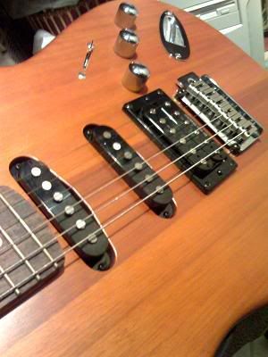
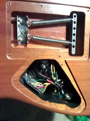
And here's the control cavity...
So, we are looking at a Mahogany Squier strat with JB seymour designed Pup at the bridge and alnico single coils in the neck and bridge...
Normally of course I advise people to test their devices out before worrying about installations and such, but having done this before and given the progress since I last built one, I feel pretty confident of a success with the mid-driver concept. At worse, if it fails, I could put it in the neck position...
The guitar has no scratch plate, as you can see so any holes in it will be permanent...I am not about to take the router to it as I did on the tester guitar on this one...so I have to fit all the circuitry and battery in this small area, as well as have sensible switching...
My solution (although push pull pots would work) is a row of three toggle switches behind the three chrome knobs and a little below...so how will I fit those in? Well, I think I can safely take a router to the control cavity set deep so as to undercut it enough to fit the switches and not effect the finish or control cavity cover plate. I could use the same technique to under cut behind the trem block to fit a battery, accessable from the trem cover...neato
The benefit of this guitar is that testing can be done before making permanent holes and such in it from wires out the back (tricky on a conventional strat)...
I am thinking of a dedicated driver (not a pickup combo like my present guitar) in the mid position....some of the details need to be ironed out yet...so the middle pickup needs to go. With this in mind I will be forced to rewire the guitar, and while I didn't wish to get too tricky, I can't resist...plus loosing the mid pickup means loosing those inbetween typically strat sounds so I feel I need to compenstae a little...anyway, I can so why not...
To this end I have ordered a "super-switch" and have been consulting with the good fella's over at Guitar Nuts 2 - Strat Mod Thread...(BTW, if you can't get enough sustainer thread here, there's another one there as well...Guitar Nuts 2 - Sustainer Thread...a lot more concise than this one...
There are a few options that will lead a variety of sounds, even with the loss of the middle pickup. Using the super switch and one toggle there is a lot you can do, I may even be able to use one of the tone controls as a progressive coil splitter for the HB...and there are novel tone controls with LC circuits to create a mid scoop, similar in sound to the inbetween sounds...so it may be all gain as far as that's concerned...
That leaves two toggles for on/off and harmonic functions for the sustainer...with a dedicated mid driver, these can be much cheaper smaller switches than the expensive 4PDT, and easier to get!!!
There is probably enough room in the control cavity for all the circuitry (a little crowded) but my intention is to have the preamp in there and the poweramp in the trem cavity, or even under the driver itself...
As I say, first things first with this...rewire the guitar and leave that mid pickup space free to experiment with...
At the moment, I am thinking thin twin blades, similar to the ideas of Juan and Avalon, parralel coils about 3mm deep and pretty close together. I may incorporate some magnetic sheilding on either side, but I want to fit it within a SC cover, perhaps with the top cut off...I even have some plans to revisit some ideas I put into the Hex devices like LED indicator and momentary switching...but perhaps that will have to wait for the next one, once the prototype prooves successful...
It's nice to be looking at participating and adding to the thread in a practical way again...I hope I can get photos but all I have is my camera phone at the moment...still the pics of the guitar didn't turn out to bad...
pete
Sounds great mate, and i can honestly see it working well in that guitar, the extra distance you have available between the bridge and neck (over my guitars atleast) i think will be more then enough to have a working mid driver there, the tests i did with my dual rail were very good up until about 10mm away from the bridge pickup, when it started to interfear with the bridge, and it looks like you have twice as much room to work in.
As for the board, i just about fitted the F/R in my cavity with no alterations (the two previously installed switches did help with that though), the board itself is atouch bigger then a 9v battery in width and height, and not as deep.
My control cavity looks does look atouch wider, but it definately looks ig enough for the job to me, best of luck with its construction mate and i'll look forward to seeing its progress
Again i've not got much to report on my own progress, still just been enjoying the mark 1 installation in what little time i've had the last couple of weeks, but im sure to start work on it again real soon.
-
Thats where im abit luckier, i have a little electronic shop down the road from me that sells most things other then IC's and J-FET's, although they do stock alot of 2n's/BC's and fortunately for me the MPF102's, otherwise i'd be in the same position you are.
I would order about 10 of them to make it worth well (and see if they have anything else useful while you're looking), £5 is alot for postage so you might aswell get your moneys worth out of it.
Best of luck with the driver in the meantime though
-
Well alot of transitors have different pin arrangements, so i would get a data sheet on that 2n and find the pins, i believe the 2n's are Source, Gate, Drain, left to right as you look at the flat side, where as my MPF102 is Drain, Source, Gate, Left to Right.
But even if the pins are right, i don't know if it will work im afraid.
A couple of pages back Col put up some links for places that sell the J201's, they might also sell the alternatives too, i would definately try to get one of them if pos.
-
Avalon, Just in case I misunderstood, and you were implying that you needed a diagram for the power stage, I dug this up
Afaict, this is the power stage I used along with my most recent agc circuit... my one has a few extra caps that I hacked on to try and cure an issue with an earlier agc attempt, but this should be fine 'as is'
Col
Thanks Col for the updated info & Schematics, its appreciated

Hopefully by the end of the week, i'll have this built, plus a new & improved Dual Rail to test with it, time permitting anyway, i'll let you know how it go's as and when it does
Thanks again mate
-
Again, fantastic work, and a fantastic description of how you went about it, a few more observations and questions in the quote below...
Strange, 'cause my G is very responsive in the lower frets, and even in normal mode, below the 7th fret, morphs to a harmonic over time (probably due to my 100uF output cap, treble bias mod to the circuit, and driving it hard with a powerful preamp, and the spiky single coil bridge pickup in the strat...)
In standard mode, the G is excellent, and does morph to harmonics too, but in harmonic mode it seems to damp the string more then anything, but its only on the G, and i can work around it.
Harmonic mode can be a little more inconsistant than normal. It works by dampening the fundumental frequencies and leaving the harmonic frequencies to be driven. This can mean that it lacks a little power in this mode and, because harmonic frequencies are faster and closer together, will be prone to problems at various points along the strings length due to the driver's position. It also may be associated with the pickups frequency response, better harmonic response may come by adjusting the bridge pickup closer to the strings overall, or problem strings like your G...could be worth experimenting with...
Yes thats a very good point, for example, the pole peices on the bridge pickup (Dimarzio Evo) are adjusted quite abit to suit my tone and style, so it might be worth fiddling with them, the G might be backed off more then some of the others.
So definately worth experimenting.
Ahhh...so, we have tested a thinner guage wire with more turns in parrallel, nice one. You have them down to 2mm thick (like col's), how wide are they (do they completely fill the bobbin?) and roughly how many turns do you think.
They are about 6mm wide (including the core) and don't even half fill the bobbin, and with the shallow height, i think it could easily have a pickup underneath, which is something i might come back to at a later date.
They were about 130 turns for 16ohms, the next dual rails i try will only be 13.5ohms, so they should be even thinner (plus i'll be going back to 3mm high coils).
So, are these wound with PVA wood glue type stuff like mine...what did you use for potting?
Im potting them in PVA wood glue as i wind them, Speed Bond to be specific, which i used to build 2 guitars with, its not fast setting as such, like the name sugests, but its cures fully in about 48 hours, but touch dry in a few hours, and i've been using this bottle (112g) for 4 years now lol.
It looks fantastic...a lot of your success is in part to your skill in the arts and crafts, top notch construction. A terrific description of how you did it to get a professional looking job, not like my long winded explanations that can intimidate people...
Well you, this thread and all the other great people here are what got me inspired to start on this, and as i've mentioned previously, i wouldn't of had a clue where to begin without it, but now im starting to get into it, and electronics in general, which i've never really gone into much, other then wiring the inside of guitars up and stuff.
So you've inspired me out of my arm chair
Yes, very close pickups on these types of guitars may well be a problem, at least at this stage of development. The way things are going with the experimentation and implementing of ideas, who knows, perhaps it is possible...
Certainly a mid driver is possible and holds many benefits...the main one being the simplified installation and wiring due to no longer needing to bypass the pickups...it would be just like installing on a single pickup guitar, once the mid pickup is removed and an alternate switching system is decided upon for the now two pickup guitar (that's what I'm looking at now...)
I'm sure we'll all be pleased to see how you go with col's circuit. I am sure you could patch it in in front of the F/R circuit in place of the lm386 one, if you wanted to test it out on this guitar BTW.
I think the mid driver is just a matter of construction, you look like the best candidate to make it happen in the short term. so go for it!!!
Other than this, and the endless refinement of the device, I guess the remote box idea comes back as a possibility. One of the main problems with the box idea was that it required a lot of wires to and from the controls and the driver in installation. Most of this associated with the bypassing of other pickups. A mid driver or single pickup guitar removes this necessity and the box could provide some with the potential to try this without drilling holes for switches and providing space for circuitry and easy battery access...if it could be built as cool as some of Tim's designs (back in the page 30's), it could even be a preferable solution...
Oh yes, and the bass sustainer, oh and the seven string sustainer, oh and the ultra small/thin surface mounted sustainer...
pete
Well i have everything i need to start on Cols circuit now (bar the lm386 side of the circuit), so that along with dual rails will be my focus for now, but im also going to be testing with another F/R circuit too, so i have plenty of options (and can test the drivers seperate to the new circuit if needed).
A working Mid Driver would be excellent, but failing that, a neck driver with pickups incorperated might be a good second (although that probably has its issues aswell).
So many options, and so little time
-
Well i've been having a ball with it this afternoon, im currently working on a track called "Rockin In The Free World" (G3 style version) with a few friends, and its just excellent, its working better now then it did in testing too.
Between standard and Harmonic mode, there are no dead spots at all, the harmonic mode is working on 5 of the 6 strings now too (it didn't work that well at all in testing), its just the G string which it doesn't fully work on (open to 14th fret'ish) in harmonic mode, but i can certainly live with that.
As for its construction, the cores are 2mm x 56mm steel cores, 2 x 16 ohm coils wired in parallel, made with 0.16 guage wire (38 SWG), made basically as two 16ohm single coil drivers, then i joined them together after winding.
The bobbings are a top and bottom made from 1mm plastic, slotted to size and length of the core (quite a nice tight fit), then glued to the core with super glue, leaving a nice 2mm tall gap for the coil to be wound in.
Once they were wound (set nicely, and fully tested), i sprayed them Black, sanded the paint back off the blades once it was dry (more for visual effect then anything), then mounted it on a bent up piece of aluminum sheet, which forms the backing plate & mounting plate, and was basically the same as the plate on the pickup that came out of it, and it uses the old pickups springs and screws.
To fix the magnets to the cores, and the driver to the backing plate, i used Evo stick, which seems to have done the job nicely.
Final results are very pleasing indeed
As for the mid drivers, im not sure i'll have a great deal of sucess on my main guitar, as the pickups are very close together, and seem to be very sencitive the drivers (its fitted with Dimarzio Fred & Paf Pro), where as the other guitar is fitted with a HS3 and a YJM, in the bridge and neck, has alot of spare room inbetween, and don't seem to mind the drivers half as much.
So this is where the real fun begins
, but with Cols circuit and some decently wound Dual Rails, who knows, maybe its possible. -
Hi guys, not done much new as far as coils and circuits go's yet, not had the time, but i have installed my first sustainer, its the 2x16ohm parallel wired fullsize humbucker, running on the Ruby/Fet (with the two extra mods from Petes circuit).
Here's how it looks :

And:

The two Switches on the body used to be coil spliters for the pickups, but i never used them, so they are now and on/off switch and Standard/Harmonic switch for the Sustainer.
Im really pleased with it, and its going to be put straight to use in some music projects too.
A big thanks to everyone who's working on this project, for making this possible, you all rock
, and this is by no means the end of my building either, now my attentions are going to be turned to a mid driver for my other guitars. -
Well i have to mail order to Maplin, but usually if you order monday-friday, in in your door the next morning, so other then the Pigme bulb, i haven't many complaints, but like you say, they only stock what sells, which isn't that handy.
I do have a shop local to me which stocks alot of electronics, but other then the MPF102, they don't stock many JFETs, but i'll check out the above links, most of the circuits seem to use the J201, so it might be worth getting a few instock.
-
...and i've just received the parts for Cols circuit from Maplin (bar 1 capacitor which they sent a Pigme bulb in place of ),
but i'll be starting work on that very soon too
Not Maplin in UK them?
Did you order the exact type of Jfet 'J201' ? thats important - also might be wise to get a few of them as they can vary so much - the tolerances are very wide.
If you want the latest version of the schematic or layout, just holler
Yeah, Maplin in the UK, i have to order all the chips from them, as they are the only ppl who stock them.
The J201's practically don't exist in the uk, or atleast as far as i can find, i'll probably have to use an MPF102 in its place as i did on the Ruby/Fet and see how it go's (not alot of choice really).
As for the latest version of the schematic and layout, any info is greatfully received, but if its alot of hassle, its nps for now mate


Sustainer Ideas
in Electronics Chat
Posted
Hello everyone, just been reading through some of the last few pages here after a long absence from the thread, its great to see plenty of ppl still experiementing, building and developing, I've not really done anything on my sustaining work since i was last here unfortunately, alot of things going on in other areas of life.
On the plus side of things, my original fullsize humbucker driver is still in my Blue Floyd rose, still working well, maybe later in the year when things hopefully start returning to normality i'll be able to pickup where i left off.
In the meantime happy sustaining everyone, and i hope you're all well