


Blackdog
-
Posts
717 -
Joined
-
Last visited
-
Days Won
6
Content Type
Profiles
News and Information
Tutorials
Product Reviews
Supplier Listings
Articles
Guitar Of The Month
Links and Resources
Forums
Gallery
Downloads
Posts posted by Blackdog
-
-
Anyone have a black P90 cover they don't need? That's all I'm missing to finally have this thing done.
You're still waiting for the cover, John ?
I can certainly donate a P90 cover ( pm me your address) if that is what it takes to push this build into the finished instruments realm.
Those inlays are beautiful, both in design and implementation.
-
Yea the V was quick. Started on a tuesday - handed it over that saterday. 4.5 days in all, I had neck blanks ready to go & some off cuts sitting waiting for one of my green builds (scrapwood builds) body & neck were all glued & fretted by the end of day 2 with the first bouts of colour going on. then clear coat on day 3, assembly on the morning of pickup. I reckon it will need the clear cut & a few more coats whe I get it back for the buffing. But screw it, he wanted it realy fast & I like a challange.
Anyway. The whole top on the PRS jobbie was chiseled, a gouge is realy the only way to get the scooped out thing I do on the bottom horn. Just havent sanded the edges or inner horns yet. Waiting to see if the customer wants a belly cut in the back before I go much further.
That is a nice carve Paulie. For the cutaway scoop (and the belly cut) I'm using rasps and cabinet scrapers, I'm not good (and too slow) with chisels and gouges. But your end results are looking great !
-
Wow ! That is one beautiful beast, WezV !
Great job ! Love the blue quilt !
-
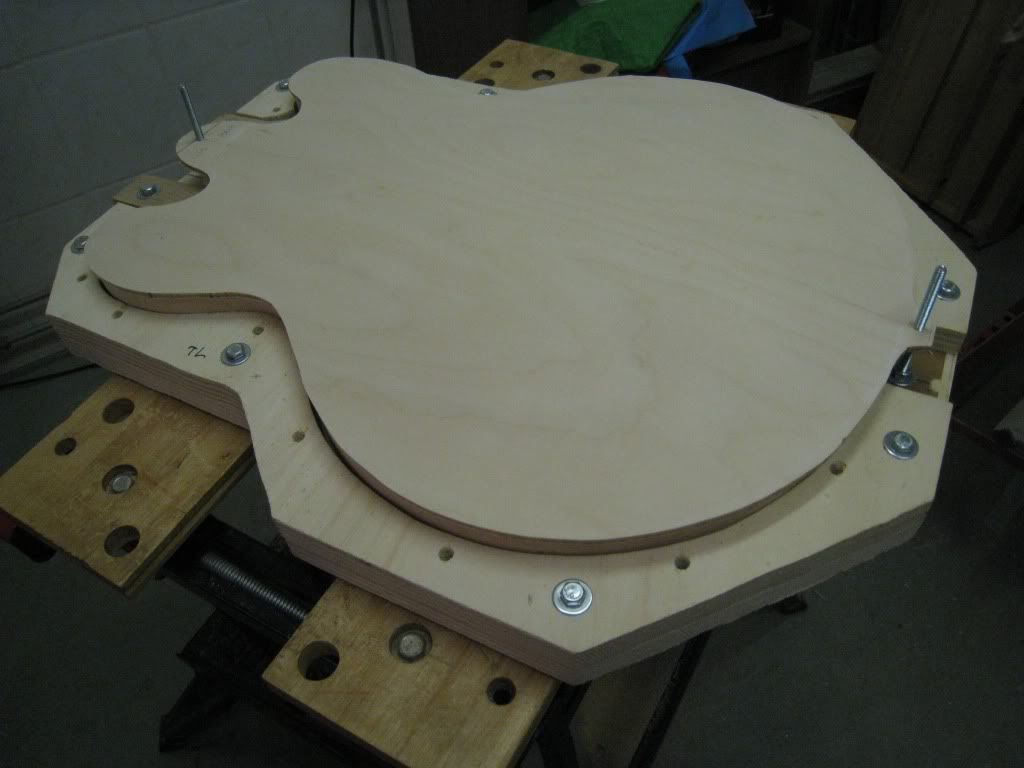
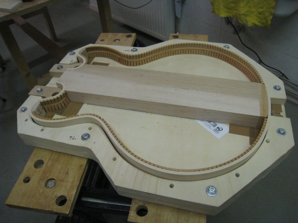
The actual gluing of the plate is as follows.
The rim assembly was placed flat in the mold and the waists were wedged out to the proper position. I added two long screws at the two index hole positions.
This is the caul.
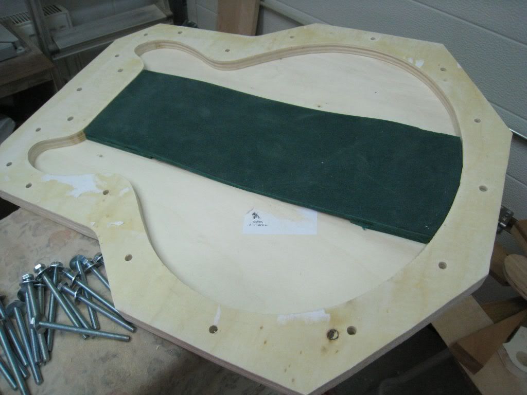
it is essentially identical to the craddle, but the array of 18 holes do not have any T-nuts. The green thing you see is a neoprene padding, thicker at the tail and neck ends.
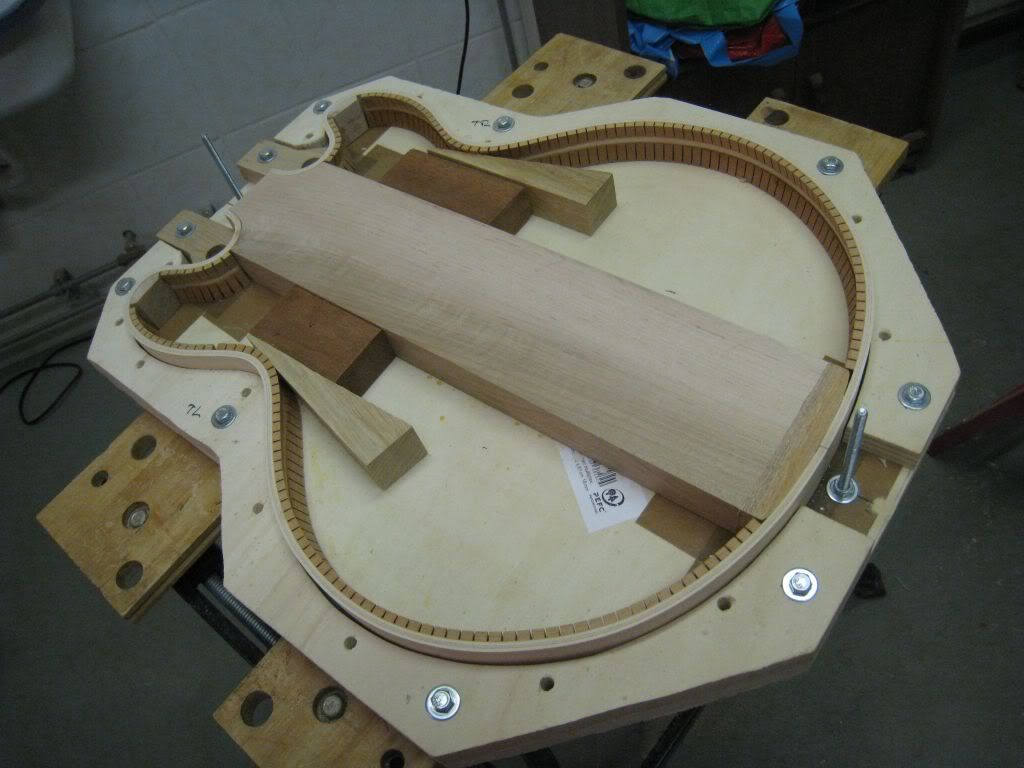
Just like the usual archtops, when gluing the plates, pressure needs to be applied all along the outline of the guitar. Normally, spool clamps are perfect for this.
But on the 335 it is also necessary to apply pressure along the centerline to ensure a good bracing to centerblock joint. I devised these set of jigs to achieve that. The caul will press the plate against the rims along the complete outline, and the neoprene padding will provide the pressure at the centerline.
I applied the glue with a roller to keep it even and to the minimum necessary. I applied it to both surfaces, lightly on one and more generously on the other. Put the plate in place on top of the rims assembly, using the index holes for alignment.
Dropped the caul on top, again using the index holes as alignment. And bolted the whole assembly together. The combination of bolts and T-nuts keep this operation reasonably fast. I'm using titebond on these, but I might switch to hide glue at one point and with that stuff you need to move fast.
And that was it for the evening.
-
The same treatment was applied to the top plate bracing. This is the top plate with the bracing already glued on:
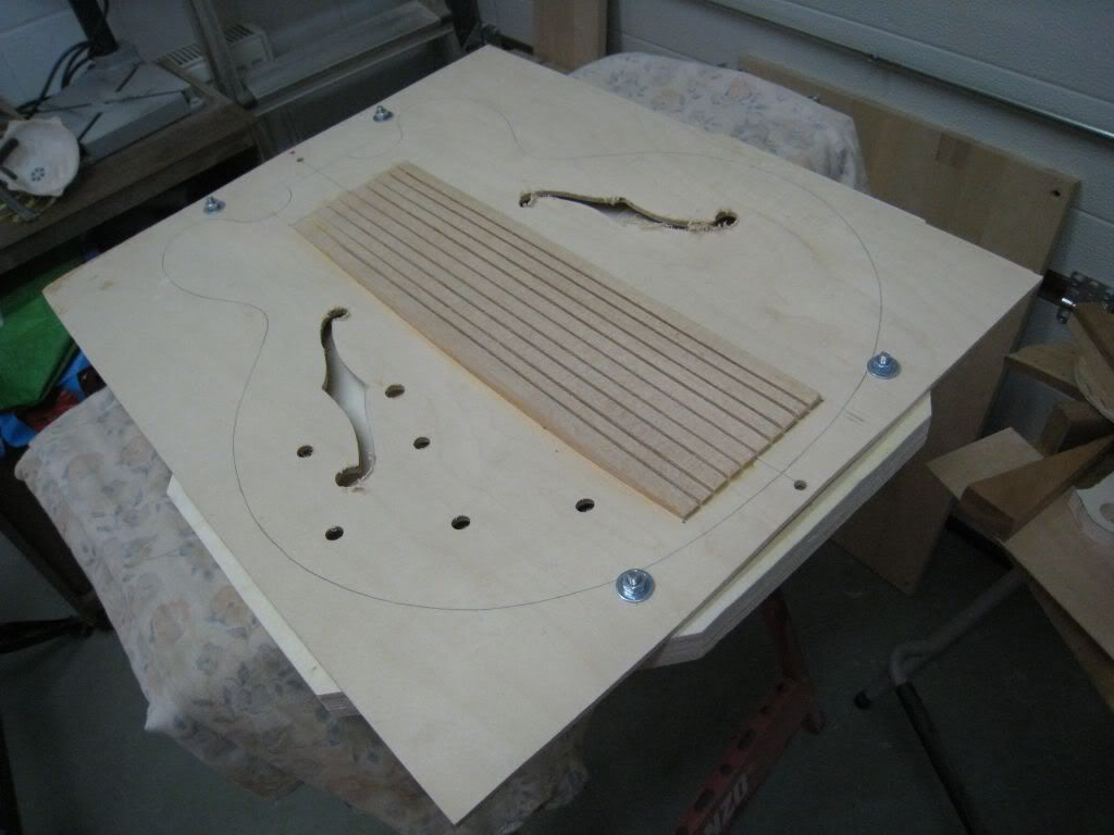
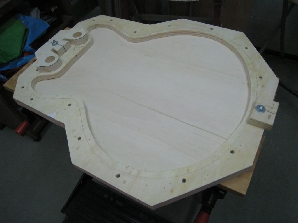
The bracings now needed to be brought flush with the plane of the body edges, tail end and neck joint. This is the setup I use to achieve that.
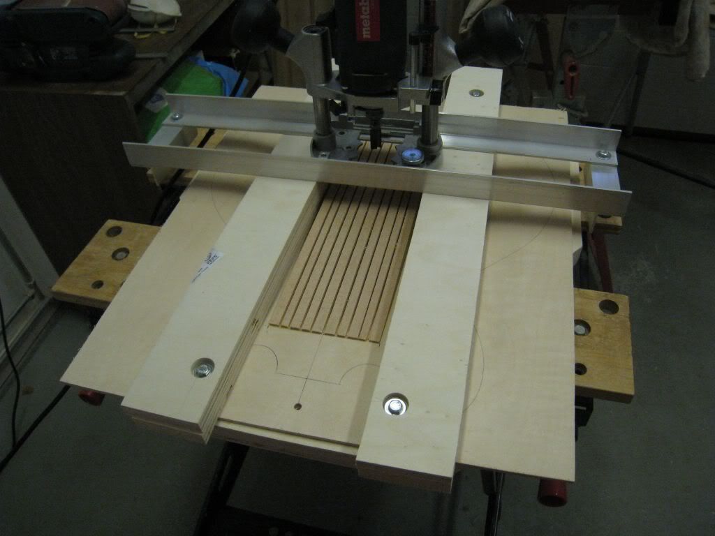
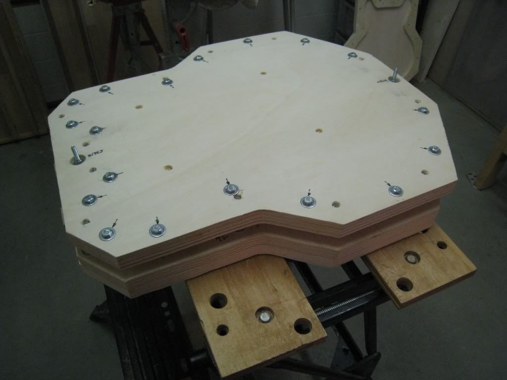
Apart of the two index holes, along the centerline, all the jigs have an array of 18 additional holes around and about 1/2" outside of the perimeter.
The mold and the craddle have T-nuts on the backs at these 18 places. I use these holes to attach different things, like the bars that held the rims down flat while gluing the centerblock, or in this jig the fences alongside the bracing to run the router on.
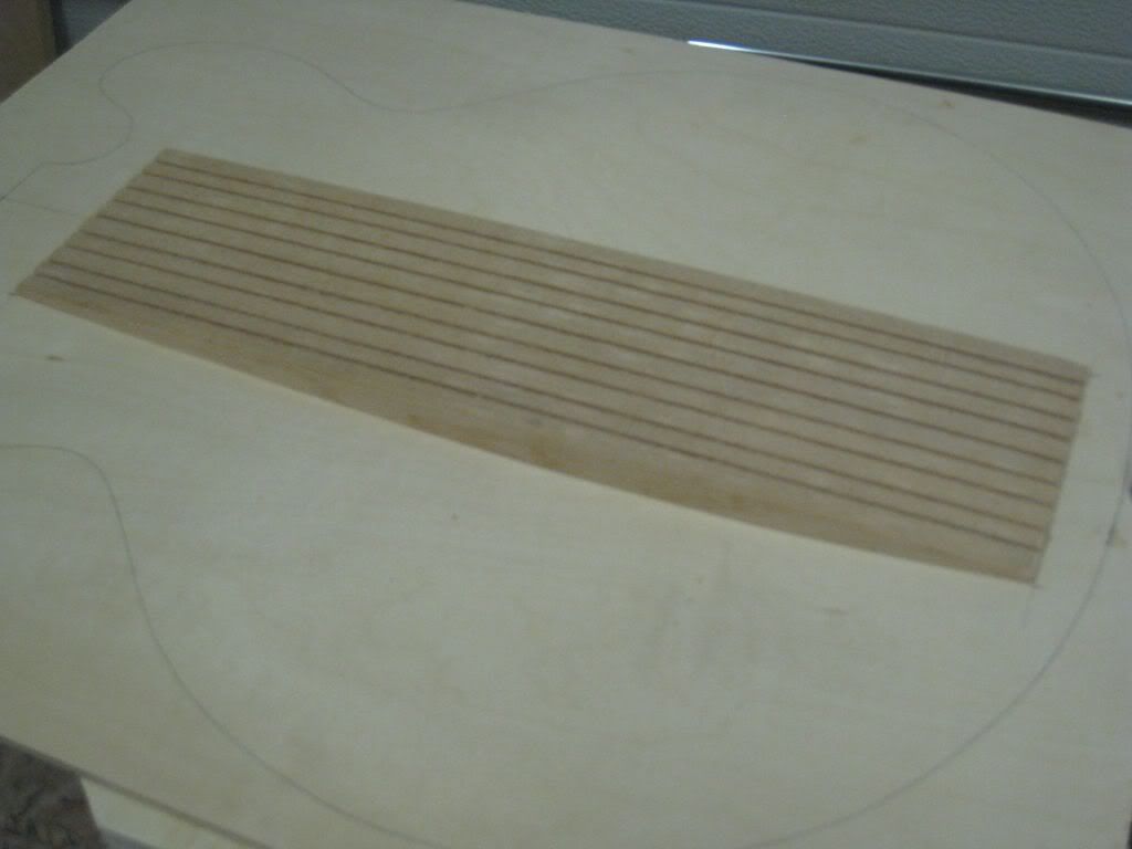
This operation is not complicated, but it needs to be done cerefully and in small steps. The kerfed spruce is quite fragile.
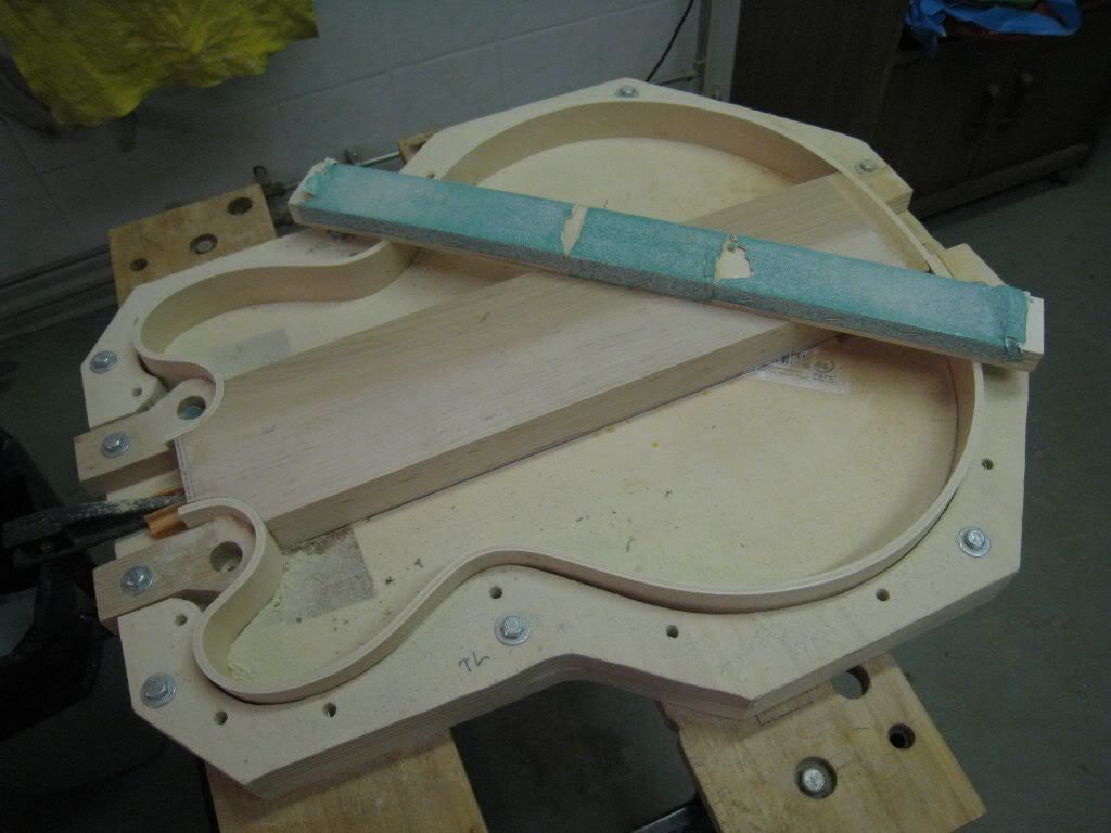
After it has been planed down it looks like this.
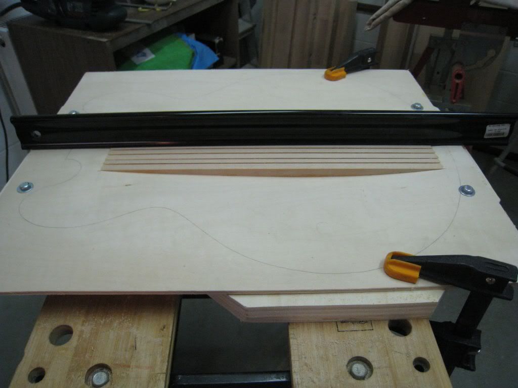
The black thing is a straight edge BTW, the curve you see is a camera lens distortion.
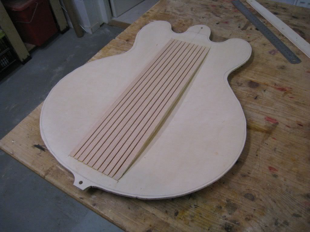
I cut the rough outline of the back plate, leaving the two tabs around the indexing holes, and this plate is ready for gluing to the rim assembly.
-
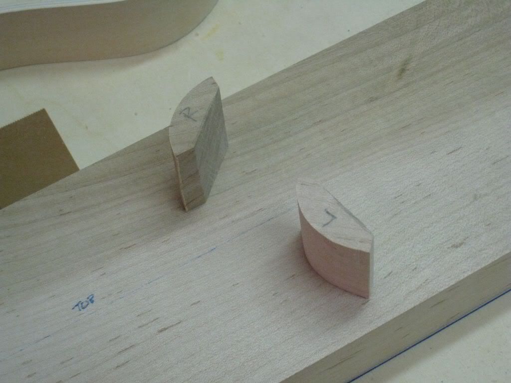
With double sided tape I fixed the spruce pieces to a backing block and drew the contour line using my little pattern ruler.
The two pieces were first band-sawed close to the contour.
And with the belt sander the first one was adjusted for a good fit to the arching of the back plate.
With some beams for distributing the pressure of the clamping along the edges and the centerline, it was glued in place.
-
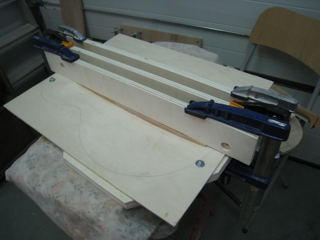
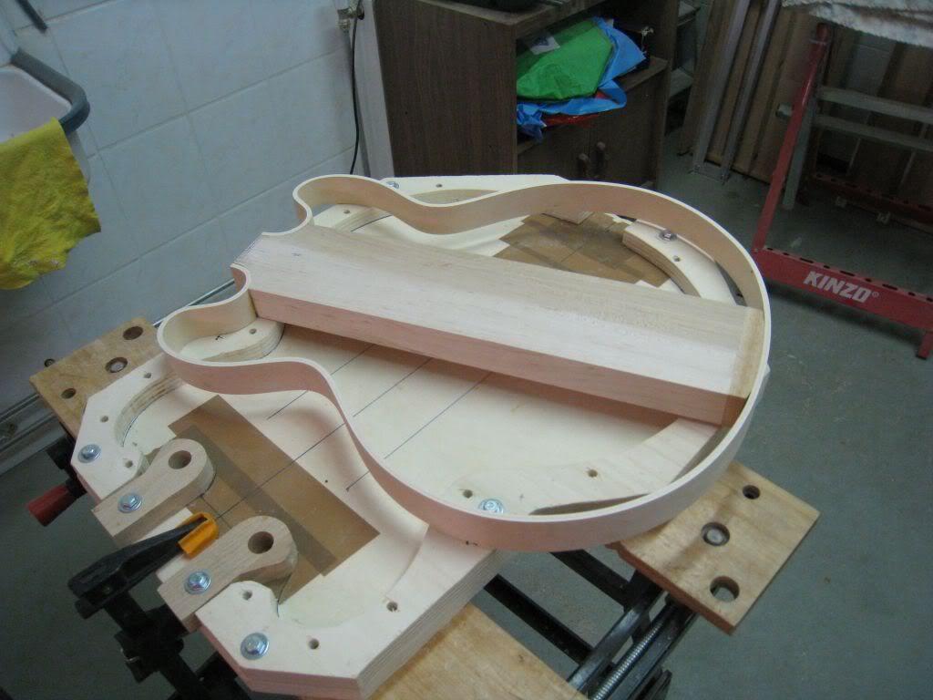
Moving on with this project.
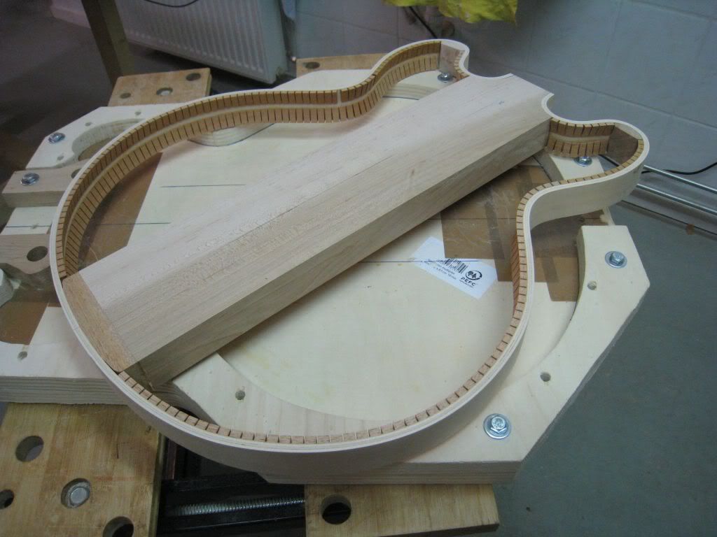
You have already seen the mold I used for the assembly of the rims and centerblock.
This one here is the craddle.
This one provides support all around the outline of the guitar. It has two indexing holes outside of the perimeter, along the centerline of the instrument. These are the alignment holes for the top and back plates, and the reference for the positioning of the rim assembly.
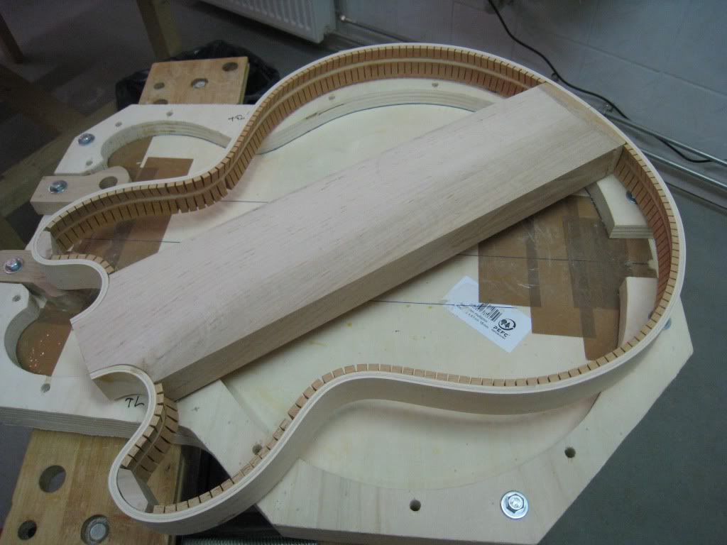
I put the back plate on the craddle, and drew the centerline and the outline using the template, referenced to the indexing holes.
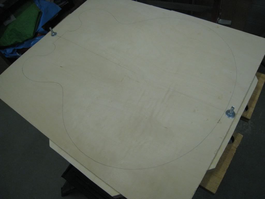
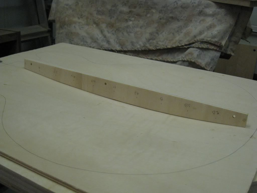
I checked that the arching of these plates is still consistent to the previous ones. I made this small "ruler" for the previous build, and it still matches pretty well.
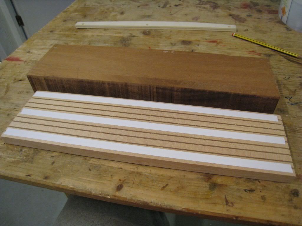
Next I split the spruce stock into the two pieces for the top and back bracings.
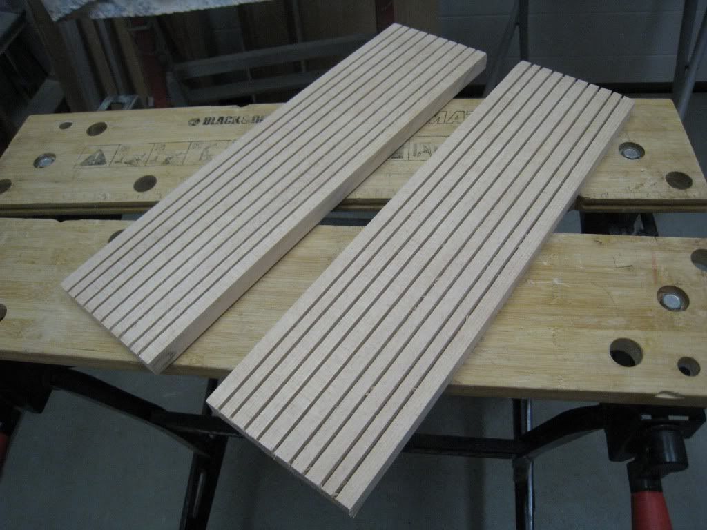
-
Now I'll have to deal with these babies. The contoured bracing spruce blocks.
Of all the tasks involved in these builds, this is clearly the one I enjoy the least.
From a factory line standpoint it is amazing that Gibson decided to put this complicated design into production.

The rims assembly is not completely unlike those required for the other laminated guitars that the company was manufacturing since earlier in the decade. Just the neck block that had to be elongated and meet with some reasonable precision with the tailblock was the only major difference.
But the 335 was a cross breed between those archtops and the Les Paul: not quite hollow, not quite solid. And that added a huge complication.
The laminated hollowbodies were meant to be electric from day one, the bracing was usually limited to just a couple of strips alongside the pickup cavities to stiffen the already stiff top even further. In the ES3x5s the bracing has to completely fill the void between the arched plates and the centerblock.
Furthermore, the 335 is kind of a solidbody in disguise: the floating bridge and trapeze tailpiece are gone, now we have top mounted ABR-1 and stop tailpiece. This means that the top-bracing-block sandwich has to provide mechanical integrity: really needs to be tight matching and solid.
The accepted historical specification calls for A-grade, quartered spruce, kerfed on one side. The un-kerfed side has to be carved to match the 3-D inner curve of the plates, the kerfed side is kept flat and glues to the centerblock.
That said, for the early examples Gibson was obviously trying different approaches. Just like the tailblock has not always been mahogany (they seem to have used anything they had available in the scrap box), sometimes the contoured bracing was made of maple, other times it was spruce, but unkerfed. A bit of Anything Goes in typical Gibson style. The kit includes the "correct" A-grade, quartered spruce stock for these.
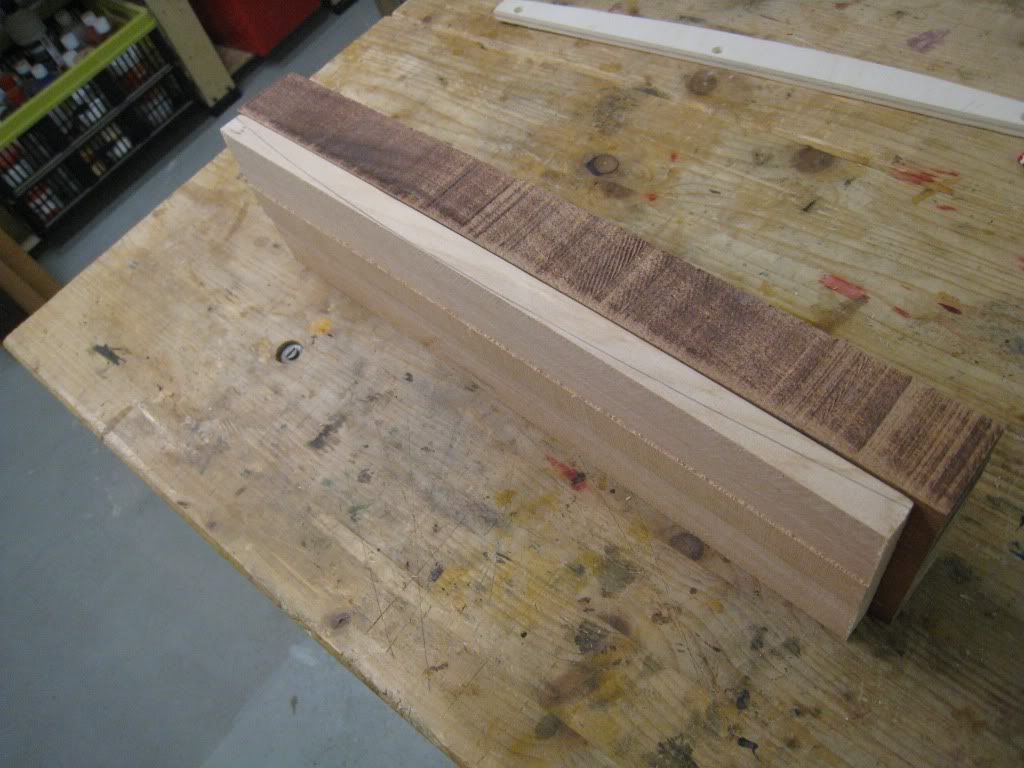
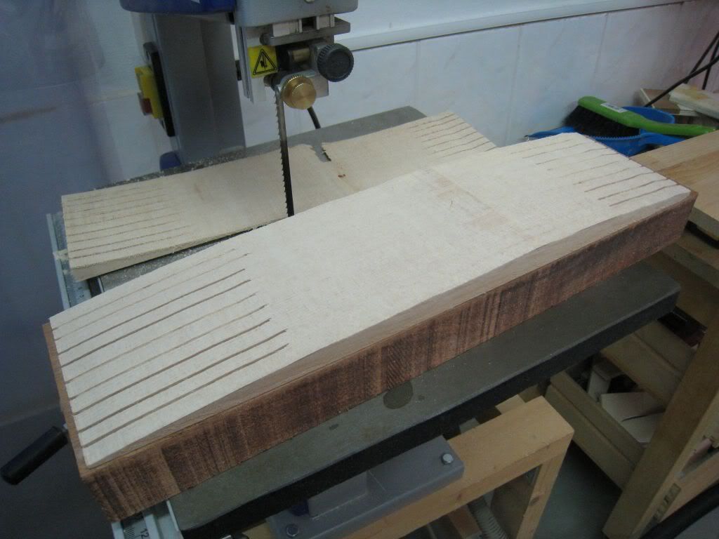
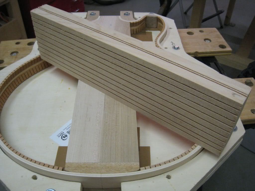
How exactly these pieces were done at the factory I have no clue, but I plan to profile the blocks on the band-saw (following the inner curve along the centerline of the plates) and then free-hand adjust the shape to fit on the belt sander. I have the feeling that this could be how they was done in the old days.
As of how it is done today, again I have no clue, but what I've seen on the modern 335 I rebuilt was a very sloppy workmanship. The spruce used is very poor quality, almost flat-sawn and the matching of the curved surface to the plate was very poor: lots of voids sometimes filled with thick glue and sometimes just an air pocket. Hopefully I can do better.
To be Continued…
-
Unfortunately, very little progress to report.
Just got the two sides nicely sanded and flush....
But at least now is official: The rims/centerblock assembly is finished and all according to vintage specs.
Now the real fun begins......
-
Well, out of the two guitars the Les Paul looks like the easy build. And that's saying something since I know they aren't easy at all.
Really enjoying both builds here. Keep rocking.
It is not REALLY difficult. But it's certainly different.
The guy that provides me with the pressed laminates sells the parts kit or the completely built body. When I was re-building the damaged 335 I did before these builds, I considered buying the assembled body but decided for the kit instead just because I wanted to try something different.
I'm glad I did (though I cursed for a good few weeks while I designed and built all the necessary molds and jigs !!).
The most difficult part is matching the contoured bracing to the inside of the top and back plates. This is coming soon.
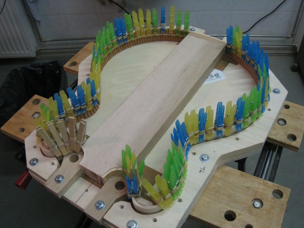
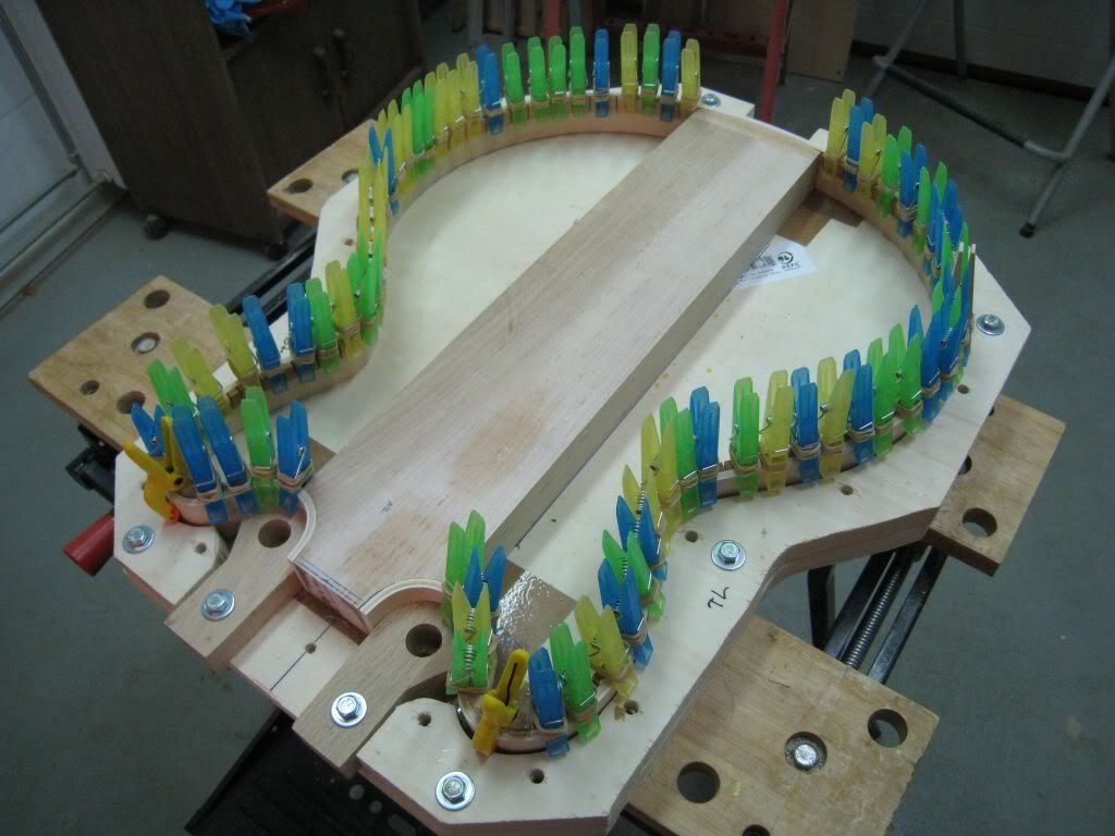
Last night the glue of the first side of kerfings was dry enough to remove the clothpins, so I quickly went with the other side. I left the sanding of both sides for today.
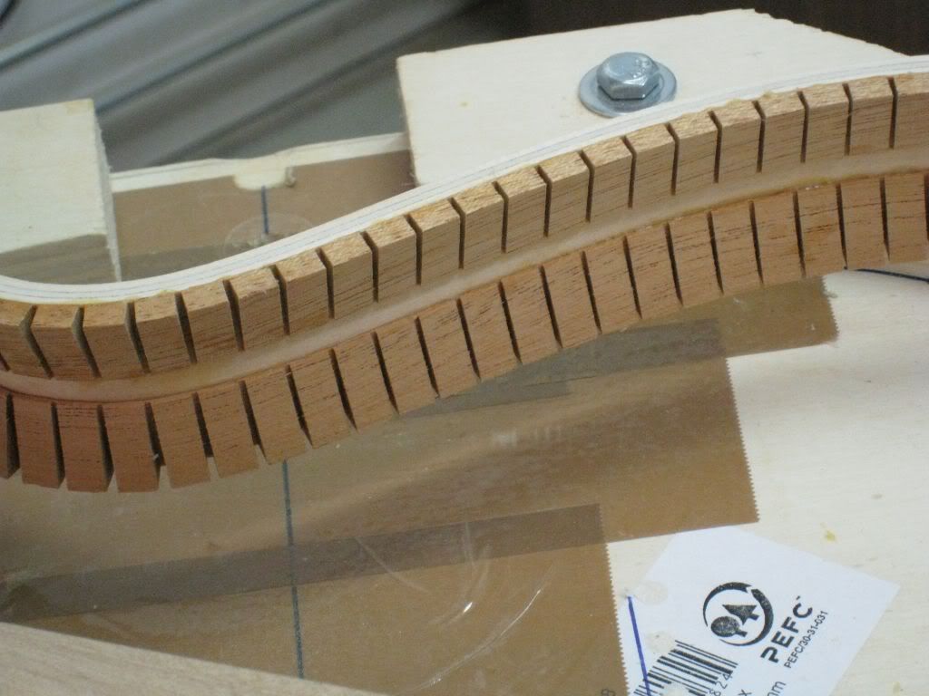
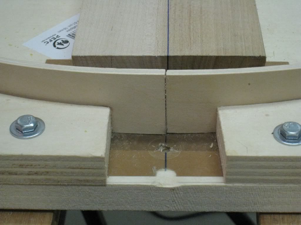
@WezV: In the last picture it's obvious there's not much free space between the two rows of kerfing on the 335. Being the Verythin, er... thinner, maybe that's why they had no kerfing ?
-
i am interested in the kerfing bit from a structural viewpoint
obviously the sides are thicker than a normal acoustic which actually gives you a similar glueing area to a normal acoustic side with kerfing
but then hofner didnt bother with kerfing on its 60's verithin's (their answer to a 335, but fully hollow) - and they have a habit of imploding and opening up at that join quite often
Interesting piece of info. I did not know that about the Verythin. Could it be that the sides are so thin that there is little room for kerfing on both sides ?
The kerfing is one of the specs of the 335 that has been reasonably stable along the model lifespan. It has always been there. In vintage days it was usually mahogany, today they use basswood.
One little aspect that changed since sometime in the early 60s is the kerfing of the horns.
These are very tight inside, and the kerfs had to be sanded in between the "blocks" to make them follow (more or less) the tight radius. Sometime in the 60s Gibson introduced a solid piece of mahogany, carved to follow the inner curve of the horn.
I used the offcuts of the maple centerblock to produce these cute little pieces. Since the match to the curve is less than perfect, I used epoxi to glue these on.
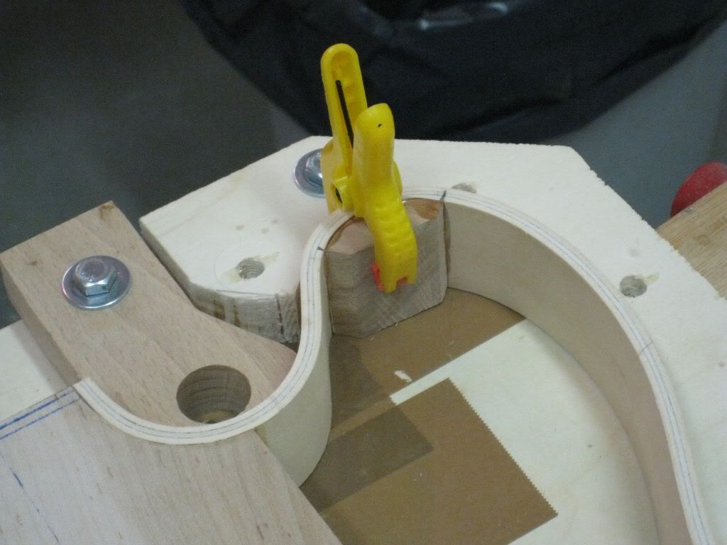
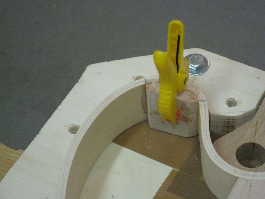
And now I'll just let the picture speak for itself...
The kerfs are slightly proud of the rims edge, tomorrow I'll sand this side flush and proceed with the other side.
-
Today, with the aid of this sophisticated tool (and 2 hours of elbow grease), the rims were sanded flush with the centerblock.
Next step will be the installation of the kerfed linings (or the "Show of the Colorful Clothpins")
-
Thanks guys ! And welcome !
I just wanted to add something I forgot to mention when I was gluing the centerblock to the rims, a bit of a critical operation as you will see.
A bit of Hollowbody trivia...
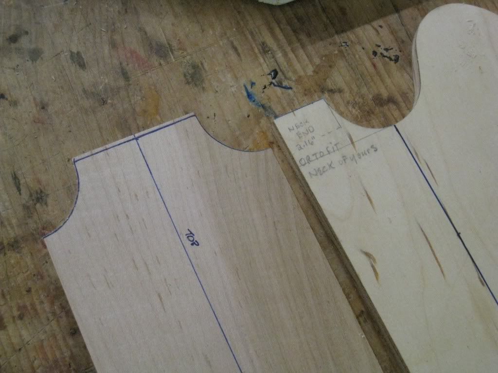
The point is that the neck joins the body at (right after) the 19th fret. The fingerboard, and hence the neck have a very specific width at that point.
This is the same width that the body needs to have at that point. But the body sides are a continuous curve from the cutaways into the tangent that would ideally be flush with the neck sides at the joint.
In reality, the highly manual nature of the construction of this guitars produced inconsistent results in these respect, and in fact the neck joint plane at the body was cut at the point where it had the right width, be it the tangent of the cutaway curve or not. This produced an inconsistency in how much the neck gets inserted into the body, and how "deep" the cutaway actually feels, which makes a sensible difference in the access to the uppermost frets while playing.
Consider these two examples, both from 1959:
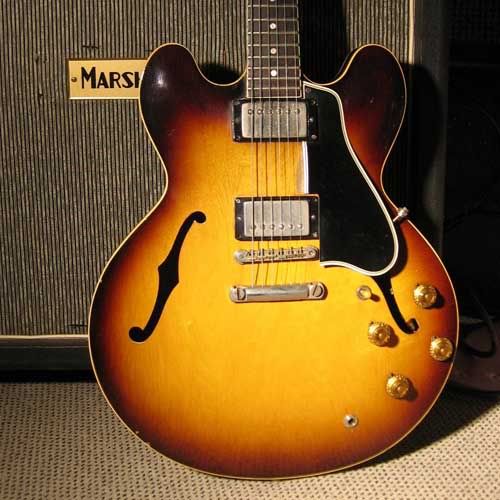
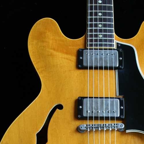
(Pictures borrowed from www.es-335.net)
On the sunburst one the bottom of the cutaways easily reaches halfway between the 21st and 22nd frets. On the blonde one (even taking into account the perspective) the bottom of the cutaways barely reach the 21st fret. The effect is also very apparent in the position of the pickguard vs. the cutaway.
Of course, the pickup routes, the bridge and the tailpiece were positioned accordingly, so only the upper fret access and the looks were affected.
To some extent this effect is still seen in today's production. Consistency being a bit better (though not as much as it should) because the complete centerblock is CNC'd these days.
I took special care with this build to get a proper upper fret access, we'll have to see how successful I've been.
-
Today's update...
The rims were marked at the centerline at the tail end. Then they were cut on the bandsaw for a good end to end match. The inside edge of the cut was filed a bit to get them to close a bit better.
Out of mahogany, with the grain running perpendicular to the centerblock, I cut the tailblock. The curved surface was rough cut with the band saw and smoothed with the belt sander.
The flat side was adjusted on the belt sander until it fitted well between the rims and the centerblock.
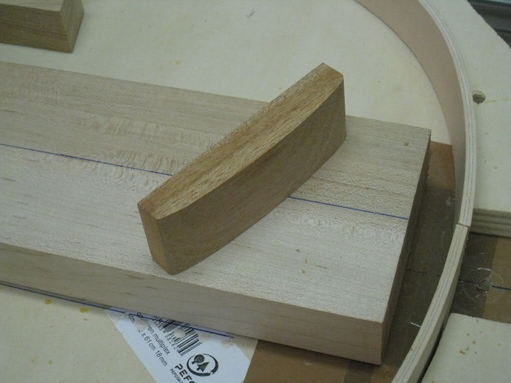
Applied the glue and clamped the assembly to press all the parts together.
In all these operations there are a couple of significant differences between the vintage way (like on this build) and the modern reissue way. On the reissues the maple centerblock is a bit wider than 5", and there is no mahogany tailblock (the maple centerblock goes all the way to the tail end against the rims).
The next step, for tomorrow, will be to sand the rims and tailblock flush to the level of the centerblock on both sides.
-
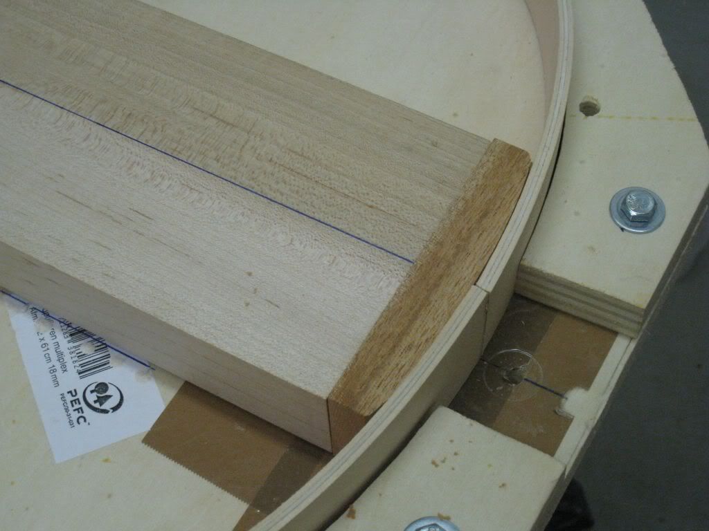
The end result now matches the curve of the inner sides of the rims.
Now is time to remove the excess length of the centerblock. This is first band-sawed, and then fine-cut with the router following a straight edge. This ensures that it is straight and square with the top surface.
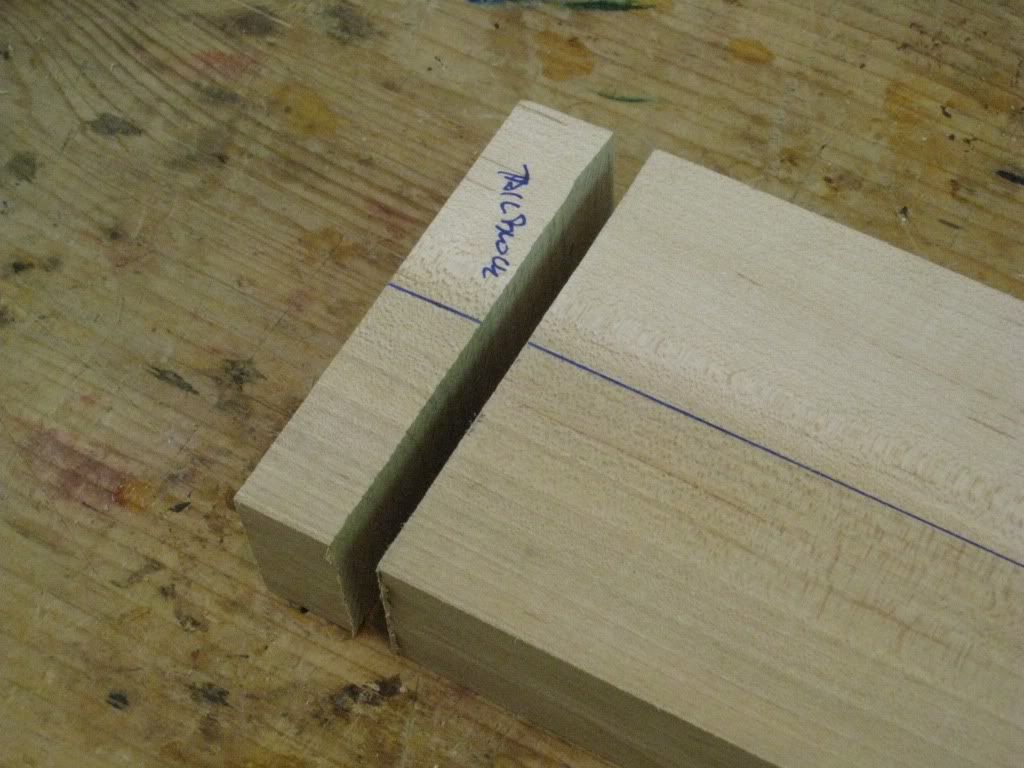
So everything is ready for gluing the centerblock to the rims at the neck edge. The centerblock is sitting on a piece of 1.6mm veneer. This is to ensure that the edges of the rims are slightly proud of the surfaces of the centerblock at both sides. These will be sanded down to the centerblock plane later.
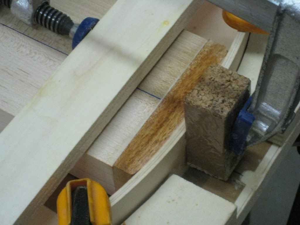
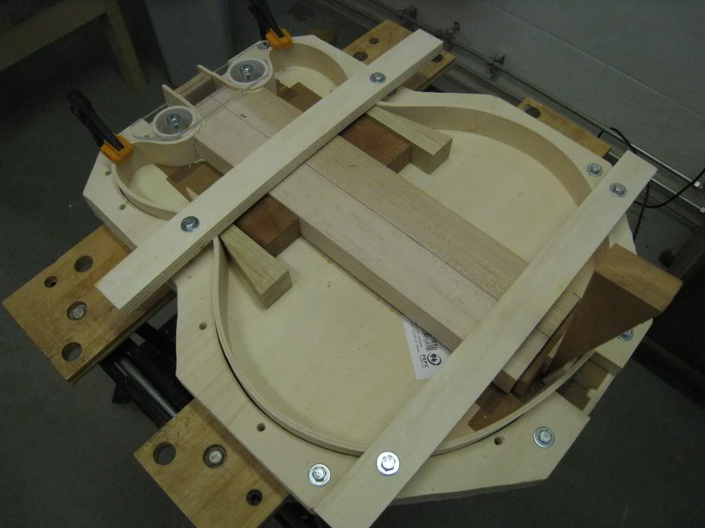
Glue is applied and everything is clamped and wedged into the right positions. The two beams across the mold ensure that the rims are well seated on the mold, the same with the two clamps on the horns. The wedge at the tail end is the one actually pushing the centerblock to press the rims against the tubes in the neck area.
The next step will be to trim the rims at the tail end to seat flush one against the other, and adjust and glue the mahogany tailpiece between the rims and the centerblock.
-
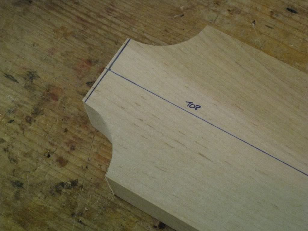
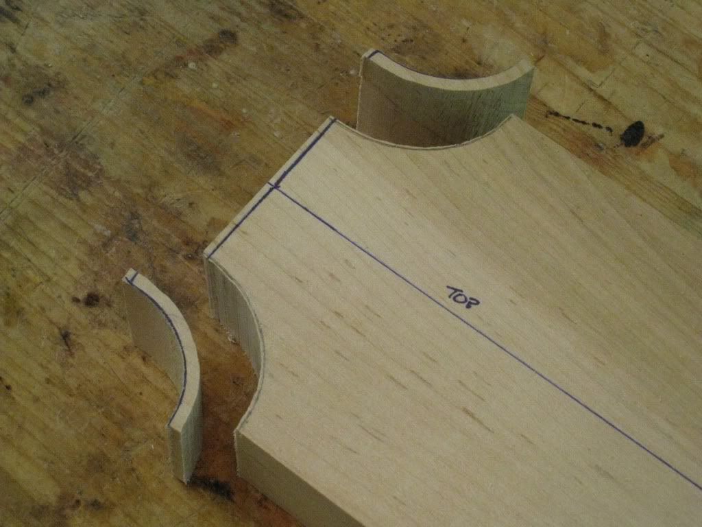
The cutaway curves on the centerblock are roughly band-sawed and fine cut with a router following the template.
But this is the external dimension. We need to make space for the width of the rims. The rims are exactly 5mm thick.
This measure is transported with the calipers to the centerblock and scribed lightly.
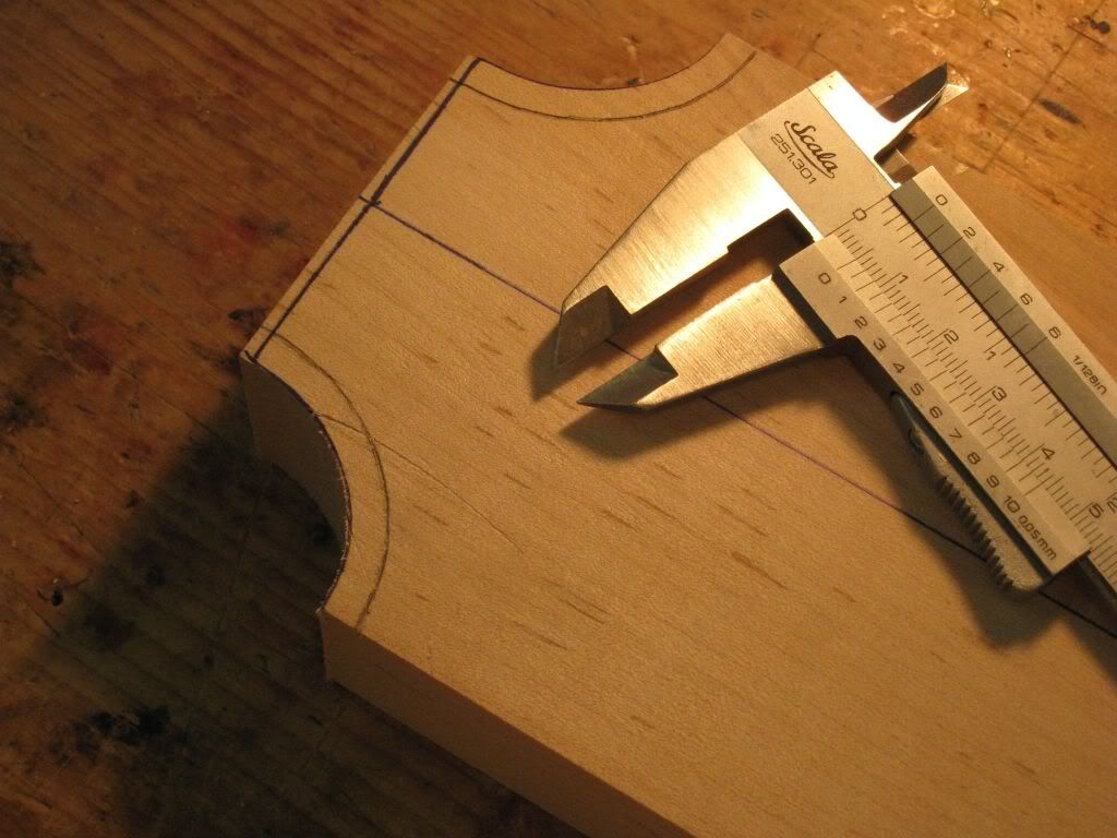
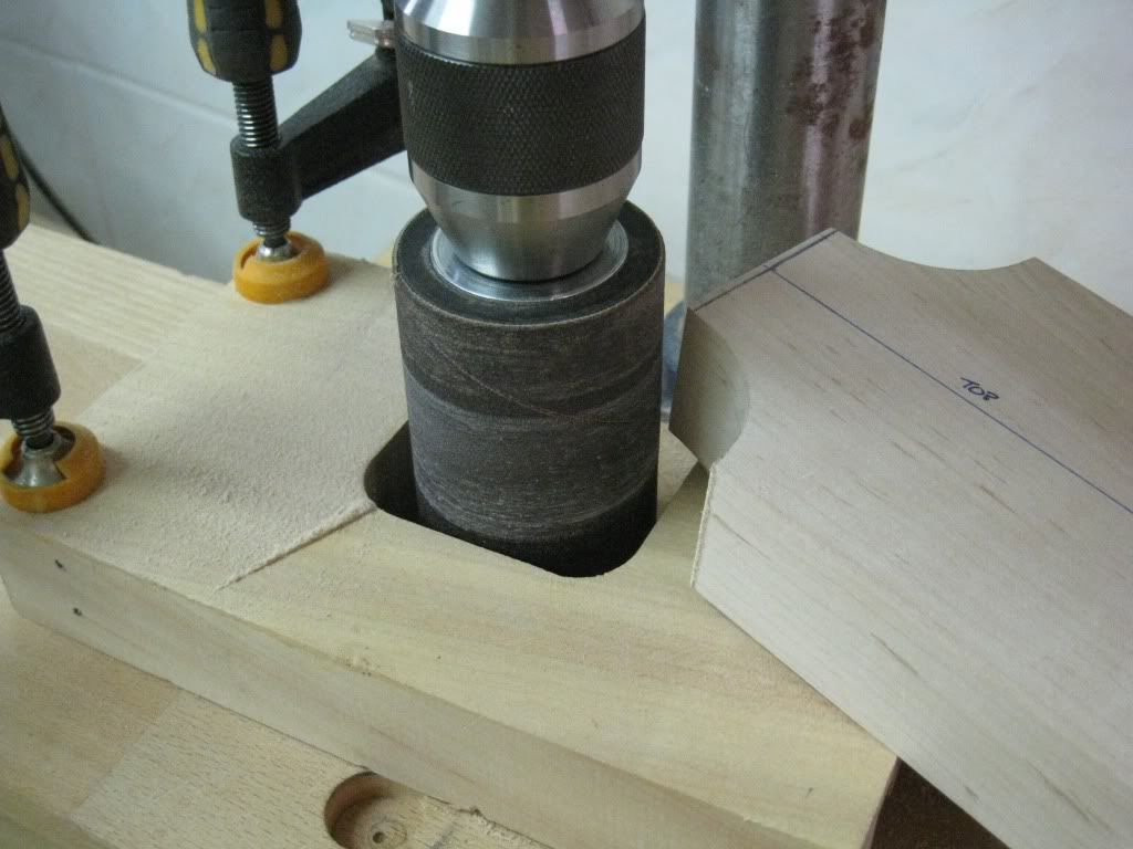
Again the excess is band-sawed away, and then adjusted with the drum sander.
-
There's not much more to be done to the LP before finishing. Just drill the hole for the toggle switch and adjust the depth of the cavity accordingly, and cut the final bone nut. Switch and nut blank should be arriving some time this week.
So there are no more excuses. This thread enters the second phase and fully becomes Semihollow.
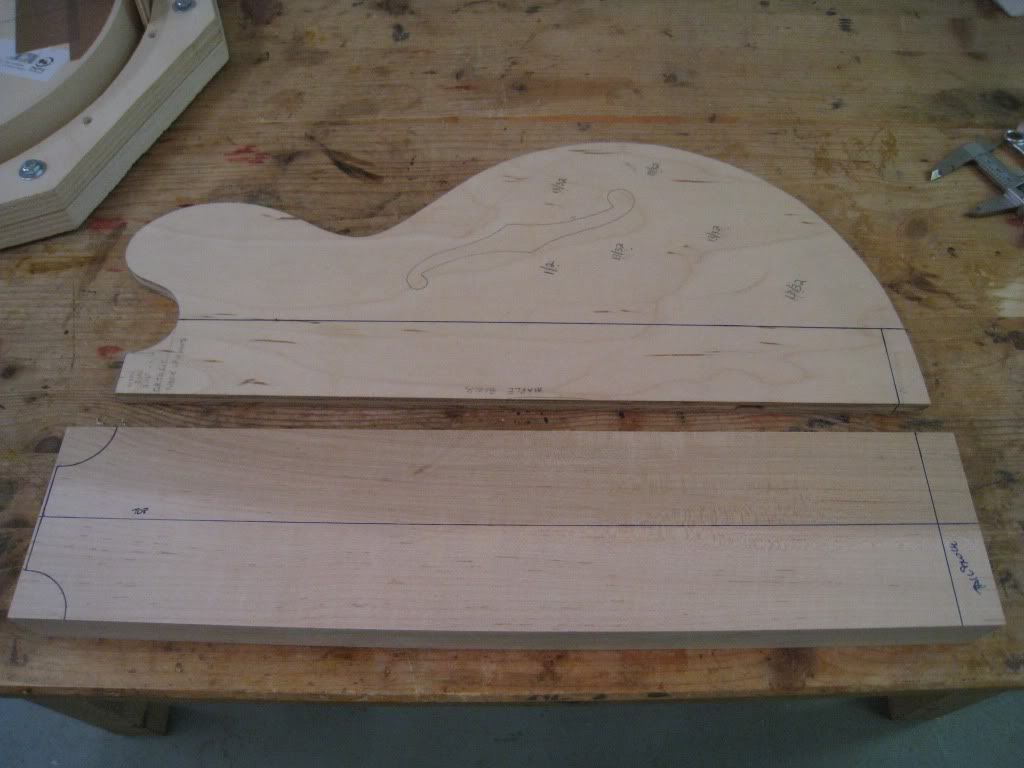
The first decision that has to be made is the thickness of the body.
Officially, Gibson listed these as being 1 3/4" thick at the rims. In reality, the vintage ones were all over the place. Some were indeed 1.75", but many were less.
I want to keep the weight of this one under control, but nothing can be done on anything except for the soft maple center block. I requested a light one, and I will build this one on the thinner side of the spectrum to further keep the weight down.
The centerblock was thinned down to 33mm. The top and back are 5mm thick each, hence the final thickness should be 43mm= 1.70".
Using the template, the curves at the cutaways are drawn. Also the final lenght of the centerblock is marked. The rest will be filled with the mahogany tailblock.
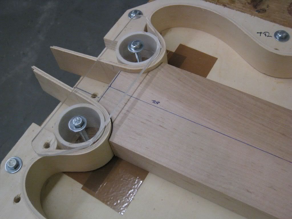
Again using the template, the mold is adjusted so that the tubes follow the curve of the cutaways.
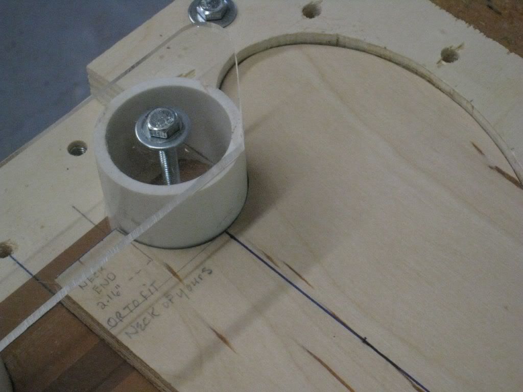
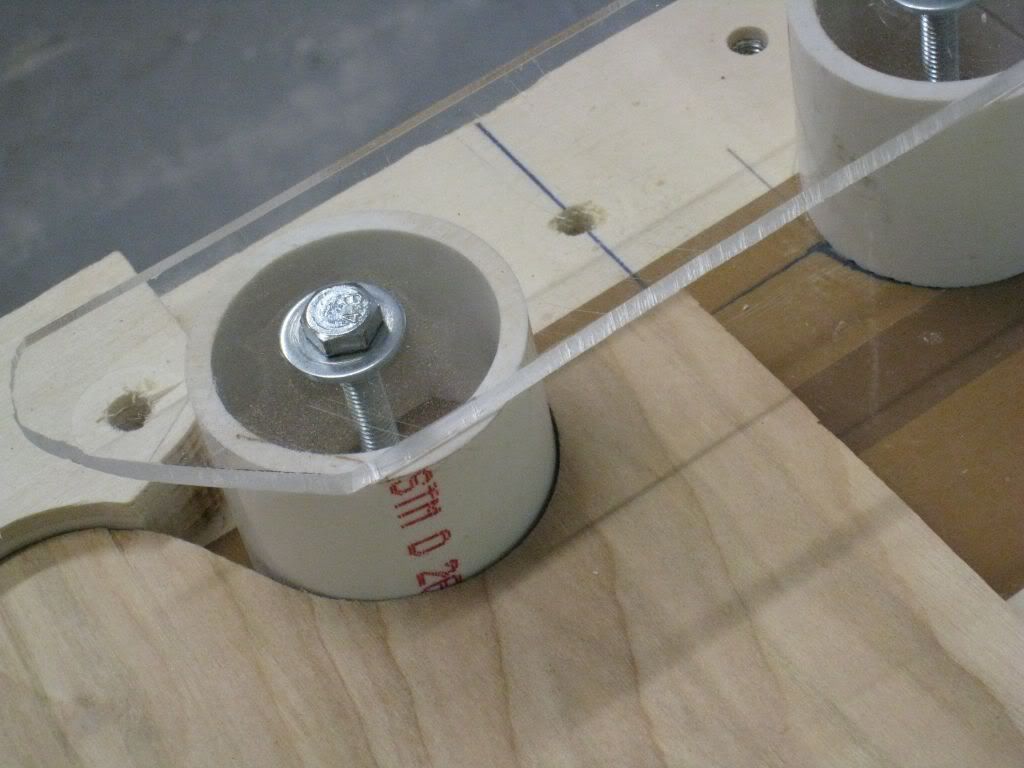
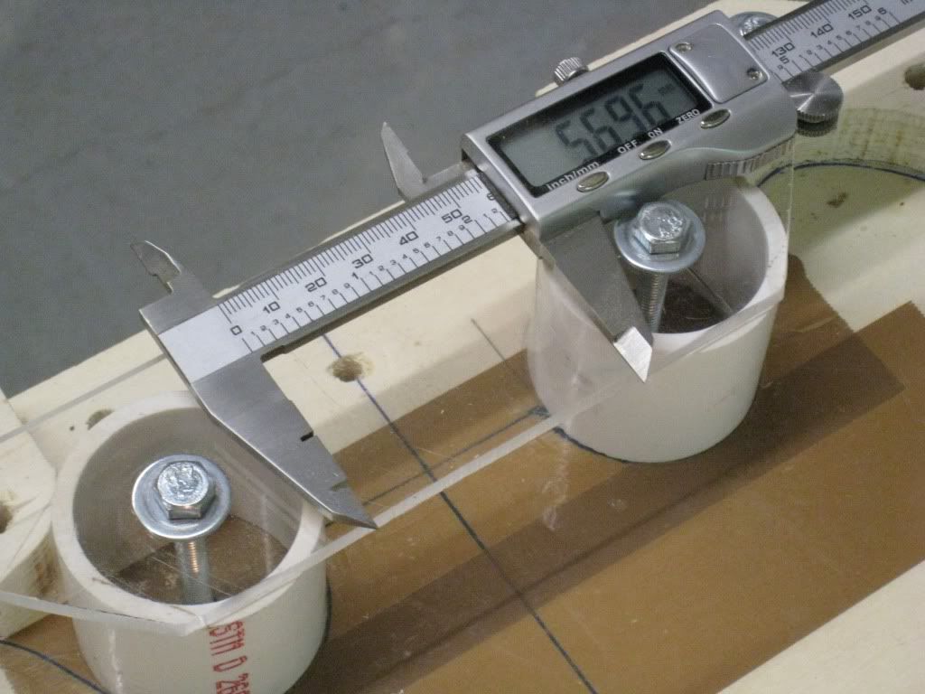
We are looking for around 56.5mm between the parallel tangents of the tubes, i.e. where the curve of the cutaways will merge into the sides of the neck. The width of the neck at the joint point is around the same.
-
I had the pickups in there already and the fretwork was done, curiosity was killing me !!
Why not assemble the thing, cut a reasonable decent nut and give it a try ??
I don't have the switch yet, so I wired it with the two volumes as a mixer.
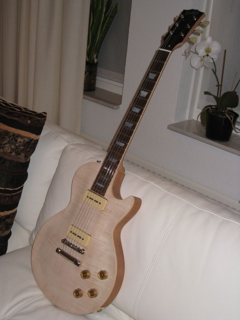
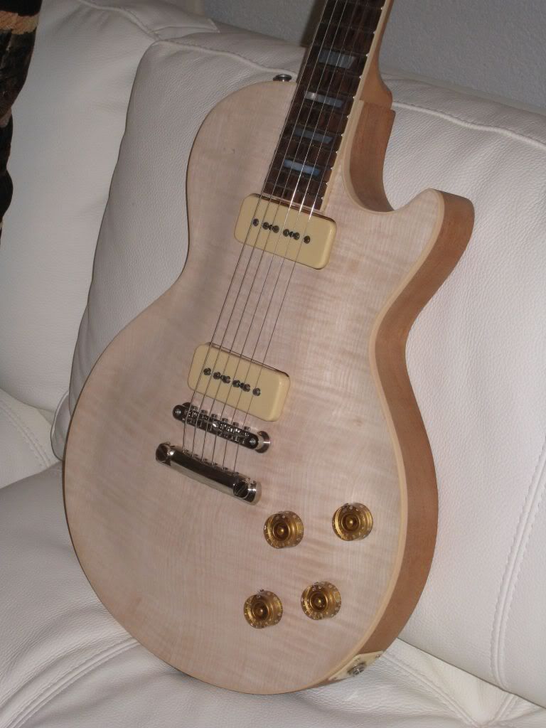
Everything fits just fine, and it sounds pretty amazing too.
It plays quite well, and the big surprise is that this Rule of 18 fret spacing seems to intonate just as well, if not better than the usual one all along the neck. I guess they weren't wrong in 1959 after all !!
-
I though it would be a good idea to fit-test the pickups in these vintage flavoured cavities. If any surprises were awaiting me it is always better to discover them before the finishing.
And I found a very nice one !!
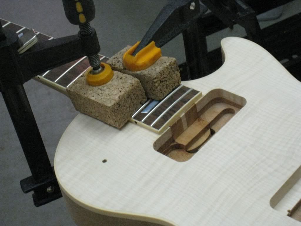
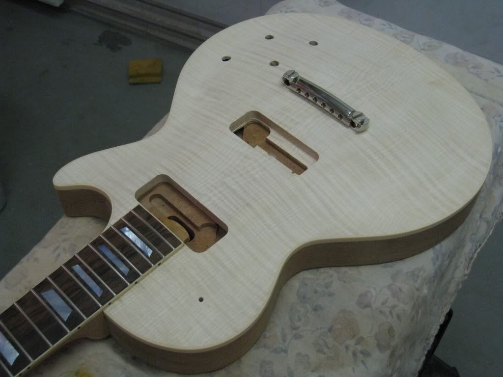
Have a look again at the neck pickup cavity:
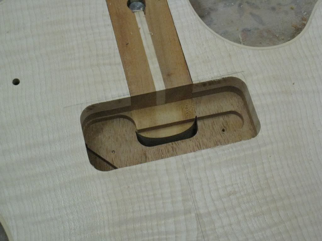
Have you wondered where the mounting screws of the P90 will fall ?
EXACTLY !!! Right in the middle of the void between the end of the tenon and the back of the mortise !!
There was no other solution but to plug that void. Out of a piece of mahogany with the proper grain orientation I had to carve a plug to fit in there and glue it in.
In the end it was just a 90 mins job.
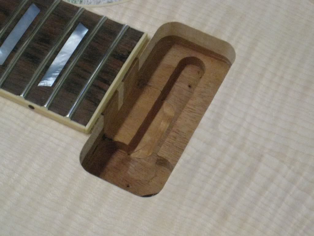
This happened because my tenon ended up a good 10mm shorter than what it was specified. I though that it would hardly make any difference, and it woudn't if I were using humbuckers...
It doesn't look vintage correct anymore, but it works ! I guess that is more important...

-
Since I am in the process of defining and procuring my spraying equipment, I decided to advance some of the tasks that I usually do after the finishing.
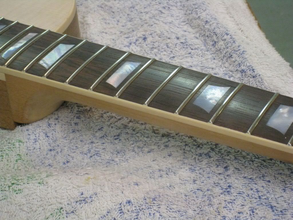
I did the detailed fretwork yesterday evening.
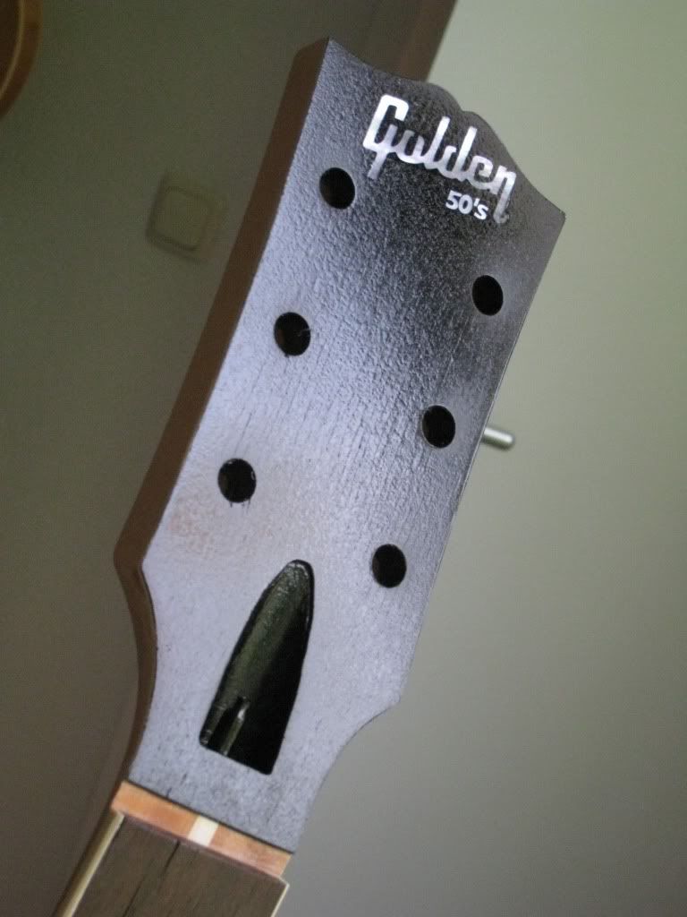
This morning I woke up early and continued with the headstock.
Like I said before, the first step is to lightly spray it black (rattle cans are perfect for this).
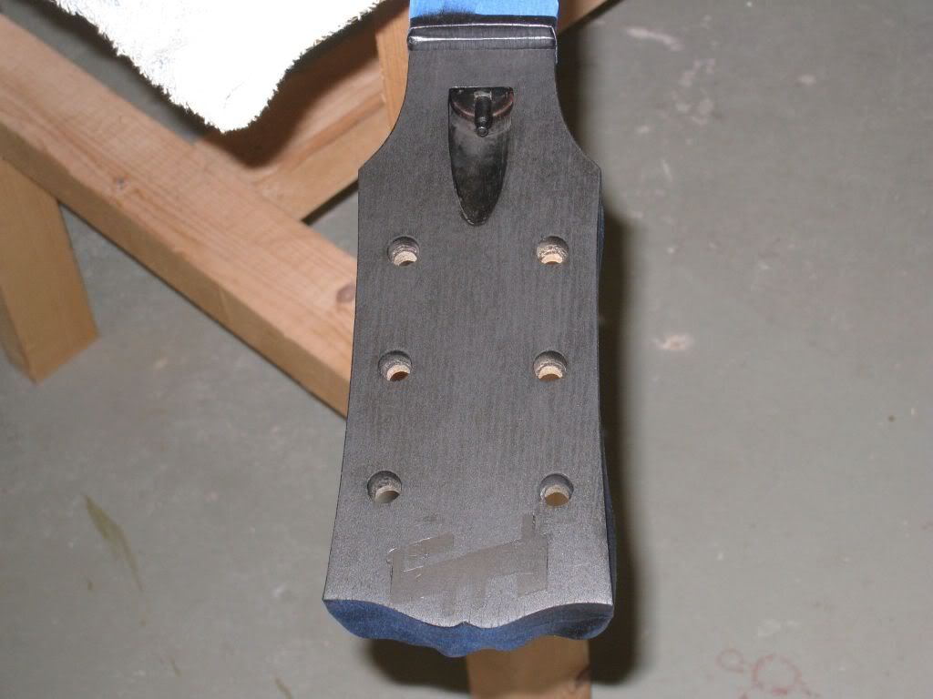
As you can see, the grain of the surface is very notorious. It looked very flat and smooth before the paint. I guess that is why holly is used for this and not maple. Oh well, with a few coats of clear it will eventually level fine.
Next the pearl has to be scraped clean. It is a pain !! What in the end worked for me was steel wool.
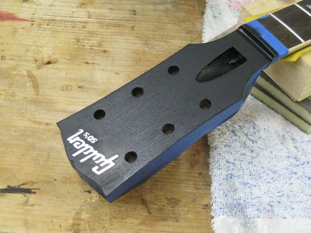
A couple of clear coats to seal the deal and it looks like this.
-
Oh well i don't post my projects here anymore. But what i did was to take a battered Gallan guitar copy of a Les paul custom, removed the plywood body and kept the solid maple top, which fortunately, had multiple binding. I made a spanish cedar body for it and a laminated spanish cedar neck, added ebony fretboard, block inlays and glued the neck.
That is a beautiful Custom, Eddie ! Great job. Must be pretty light with the cedar body.
A black LPC is so elegant...
-
Looking really good Dog. You've got me chompin' at the bit to do another LP, one a little more vintage 59-ish. I'm staying tuned to this one.
Do it man ! Good Les Pauls are hard to beat !
I´ve been drooling over this thread. I love it
I sooooo wanna build another les paul custom...but the multiple bound body scares me! hehehe
What do you mean "another" ?? There is a thread I have missed methinks...
I have to admit that the multi-ply binding is worrying me a bit too, the 355 will have the same binding style as a LP Custom.
Specially worried by the fact that in the 355 you can't afford to do it all as binding (same depth, 1/4"). You have to keep just the outer layer as binding and the inner multi lams have to be applied as purfling (much shallower) to avoid weakening the top to sides joint too much. Means that after finishing the body I'll have to take it to the router to route a two-level stepped channel around... Sounds scary...
-
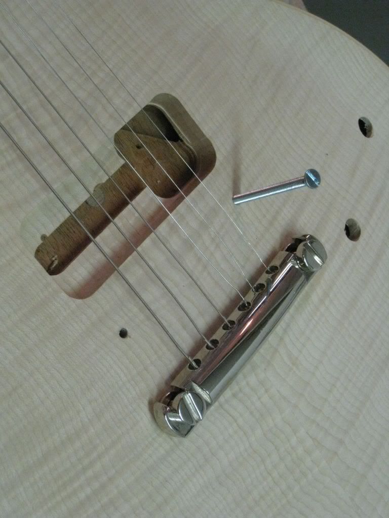
The screws were cut to length (long enough to reach into the mahogany), and using the thumbwhell locked with an additional M4 nut, the posts were driven into the top.
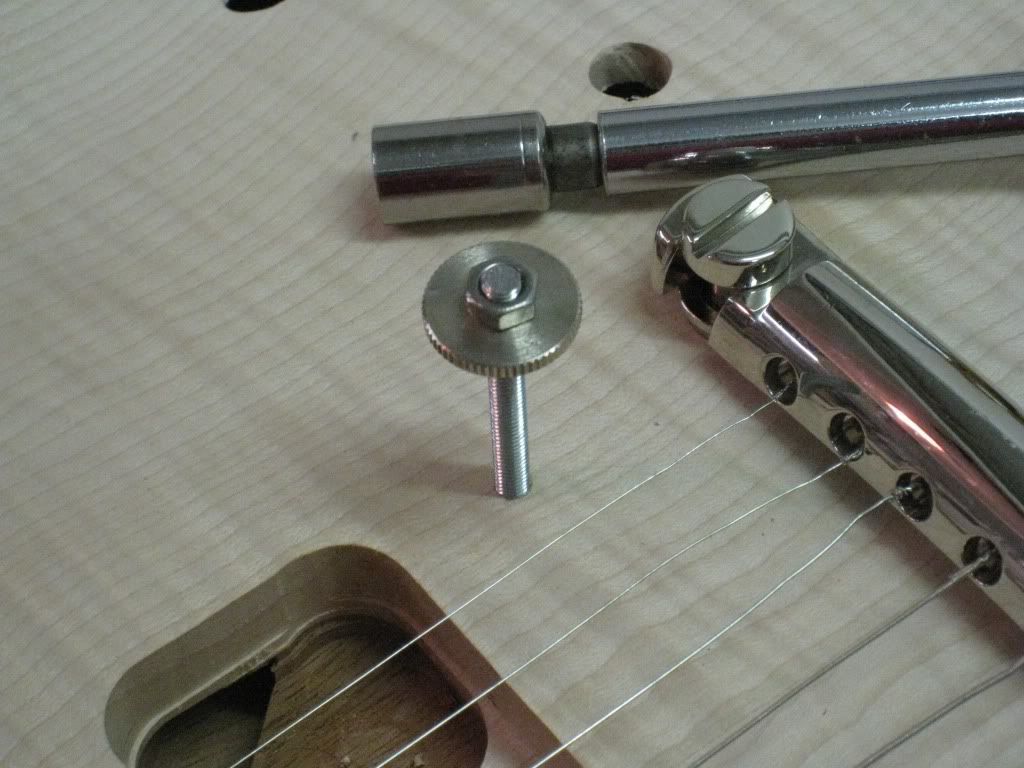
When just about 12-13 mm of the screws remain exposed, the locking nut was removed and the bridge put in place.
And I think I can call it a day.....
-
I absolutely love your builds! The attention to detail in your work is something I try for in every project I do.
I'll get there some day
Thanks Firefly. I'm flattered you find inspiring the way I work. I do take my time, but these builds are still not perfect, mind you. I still make mistakes here and there, I try not to repeat them. So far I managed to make all new mistakes every time...
Progress report: after another carving session for the top and the neck, some sanding and a bit of basic fretwork, the neck was ready for setting.
Point of no return. This was last night.
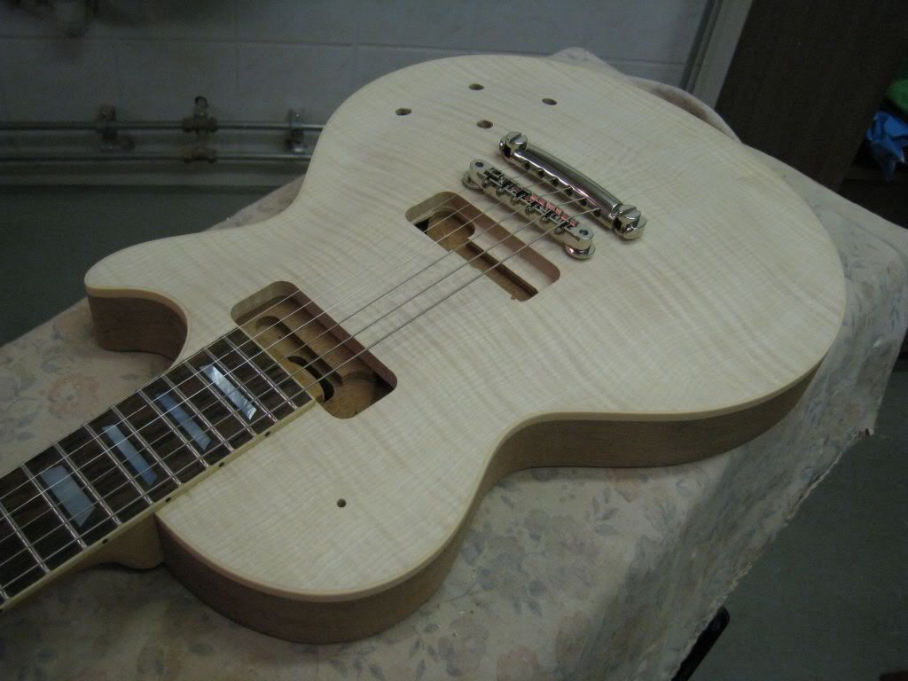
Next task for today was to install the tailpiece. I positioned the posts following John Catto's plan. The bass side post is a couple of mm further back than the treble post. This is how the originals were made, apparently to visually offset the slant of the bridge a bit. This applied to all the STP/TOM equipped guitars, not only Les Pauls. It is one of the details that the current reissues are not implementing yet. Maybe next year's models...
Of course, the treble post bushing was installed after drilling the hole and threading the ground wire into the control cavity.
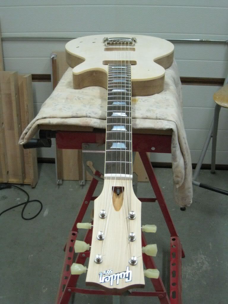
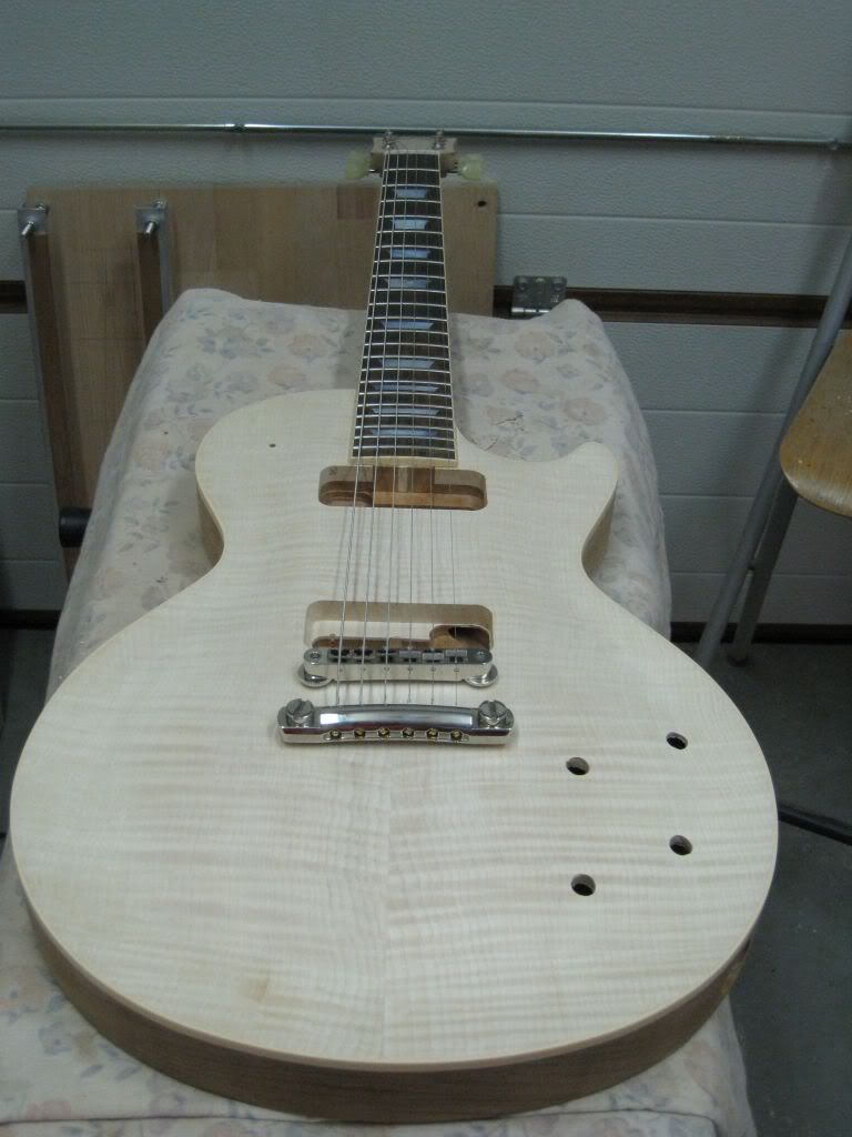
Positioning the bridge is a interactive task, as I mentioned. Installed the tuners first, and a cheap pre-cut plastic nut loose in it's slot. Stringed the guitar with the bridge just sitting on the top with a couple of veneer spacers to separate the strings from the fretboard.
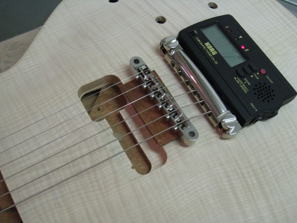
Tuned to pitch.
Adjusted the high e saddle all the way to the front position, and backed it a couple of turns for margin.
Adjusted the low e saddle all the way to the back iopstion, and backed it a couple of turns for margin.
Then positioned the bridge so that these two strings intonated properly. That's the correct position for the bridge.
With the bridge held in place by the pressure of the strings, it's holes can be used as the guides for drilling the top. This is a metric Faber bridge, the posts are 4mm. I used a 3.5mm drill bit and drilled perpendicular to the neck plane (approximately), deep enough to reach into the mahogany back.
I'm using 40mm long M4 steel screws as posts, the screws themselves can be used for tapping the holes.


A Pair Of Gibby Tribute Builds.
in In Progress and Finished Work
Posted
Hey Thanks !
The Red Special is such a fascinating piece of history, in every possible sense ! Your plan sounds interesting and challenging.
Regarding my own ES knowledge, I can't chalk it up to personal experience. Which, in my case, would be limited to the modern construction methods, most notably from the 2010 broken one that I completely took apart to rebuild.
By far most of the info I'm relaying in this thread comes from good old internet wisdom. Several threads in a couple of sites, and some articles and factory tour videos tell a lot of the story.
With respect to threads, by far the most educational are the ES335TD and 59 LP builds by user Preeb at the Telecaster Forum. That guy is incredibly comprehensive in his research of the models before he starts a build. He strives to duplicate every single construction detail and quirk of the originals. I don't know how much he charges for his builds, but I would guess they are not cheap (and deservedly so).
What I'm trying to achieve with the builds in this thread is something more like a good reissue, hopefully a bit better than Gibson's own, while keeping the thread informative and hopefully fun.
As a player, after a PRS(-ish) period (which was also reflected in my builder approach) I pretty much rediscovered my first love for the Gibsons.
I always loved the LP, and I'll never be without one (or several), but now I am a bit fascinated with these semihollows. I think it is the most versatile design that came from the Gibson company.
I like that it has always been a bit of a difficult child, complicated to build in a factory environment, which produced a lot of inconsistencies along the years. It doesn't have much nobility in it (I mean, come on: plywood !! soft maple, plastic bindings...), and still is a professional grade instrument that gets the job done every time.
Right now, my reconstructed 335 is my number one. I'm expecting these two to join it pretty soon (the LP is completely assembled, though unfinished, and it plays great and sounds amazing).