


jer7440
-
Posts
1,056 -
Joined
-
Last visited
Content Type
Profiles
News and Information
Tutorials
Product Reviews
Supplier Listings
Articles
Guitar Of The Month
Links and Resources
Forums
Gallery
Downloads
Posts posted by jer7440
-
-
I use the same as jer7440 - a 6", 11" and 18". I use those for a lot of things, they come in really handy.
I also have the 18". Very handy!
-
mcheck thi out...gotta give those guys credit...aw4some attitudes towards the fans...
UI would love to be ib that dudes place
That is fantastic isn't it, there are not many bands that would take the time to let a fan jam with them, that dude can play and he got a great story to tell that day.
Looks like they have done quite a bit of that....really cool.
-
Lookin good Geo.
-
I have used my radom orbit sander and a small vice to rough shape my last nut. Worked out great. I finished the rest by hand.
-
I use this:
It was a leftover from my RC airplane days. Just stick some adhesive sand paper to it and your good to go. At 5 bucks the price is pretty nice too.
-
that is awesome...nice job
-
Thanks for the pics Jon. Do you have any idea how they do the back of the neck? I gets a little trickier with an angled head stock.
-
Hey guys, I'm seeing more and more talk about cnc machines around here so I thought I would share the latest jig I came up with for cutting guitar bodies in my cnc.
I had been using double stick tape to stick my body and neck blanks down. This works out ok, but I had one neck blank tear loose and it destroyed itself and I had another body blank move a little...so it was time to come up with something more positive.
Another thing I was taking into consideration was the fact that my cnc machine is actually a metal cutting machine. This means 2 things for me: 1.) the machine is always a mess. 2.) there are 2 vises mounted to the machine at all times. All this means its a giant pain to get the machine ready to cut guitar stuff if I don't use the vises for my work holding ( at least 1 hour of cleaning before I can even start to set things up).
So my jig started with a 2' long piece of 1 1/2" X 4" steel. I drilled and tapped 2, 1/2"-13 holes on the center line of this piece of steel. Next my partner in crime, PRSguy, hooked me up with a chunk of plywood. The plywood is about 2'x2' and is a double thickness of 3/4" glued together for a 1 1/2" thickness. I transferred the 2 tapped holes from the steel onto the plywood centerline.
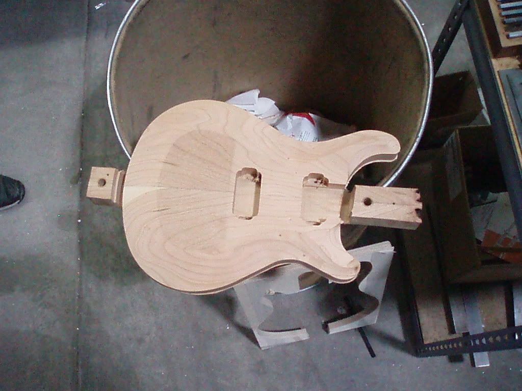
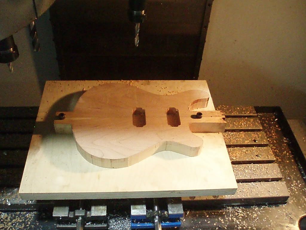
The 3rd part of my jig is a template that I use to prep my body blank for machining. Here is a picture of this template attached to a body blank.
As you can see the template has a tab at each end of the guitar and each tab has a 1/2" hole in it that corresponds to the 2 holes in the rest of the jig. I attach the template to my body blank with a couple of screws then I use the holes in the template to transfer the holes to my body blank. Then I trace around the template. Then I remove the template and cut out the body on the bandsaw leaving about 1/8" outside of the traced line. The blank is now ready to go to the mill
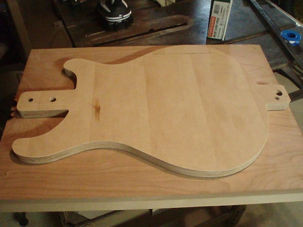
The steel part of the jig gets clamped in the 2 vices on the mill. Next is the 2'x2' piece of plywood...this acts like a table to fully support the body blank. Then we add the body blank. The steel is held tight in the vice and the plywood and the blank are attached to steel with 2, 1/2" bolts. I start out the guitar face down and from here I machine the control cavity.
bandsawed blank w/ control cavity machined
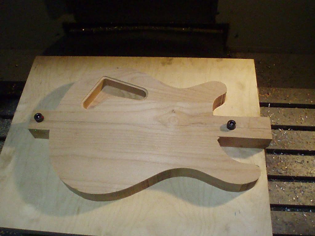
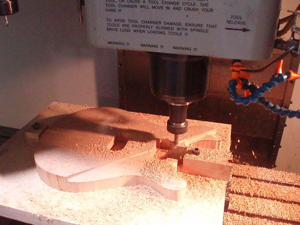
Since the bolts are on the center line of the guitar all I have to do is unbolt the blank, flip it over and I'm ready to start cutting the other side. Here are a couple of pics of machining the top side.
neck pocket and starting to carve
Once the carving is complete it is time to finish the outside boundary of the guitar. The entire outside contour of the guitar is machined...even cutting through the mounting tabs. We finished almost the whole outside contour leaving only 1/8" at the bottom to hold the guitar to the mounting tabs.
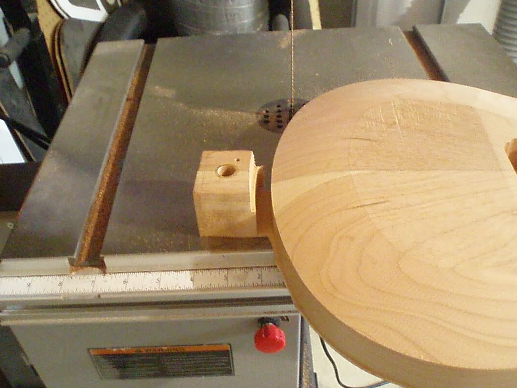
At this point it was back to the bandsaw to trim off the mounting tabs.
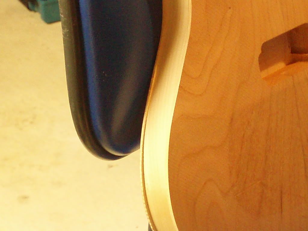
Here is a close up of whats left after the tabs are sawed off.
A quick trip to the router table and the flush trim bit and everything is clean and ready for finish sanding. Anyway, this is what I came up with and it really worked out great. I was much safer than double stick tape...probably more accurate too. Next up: a neck jig that uses a similar type setup.
-
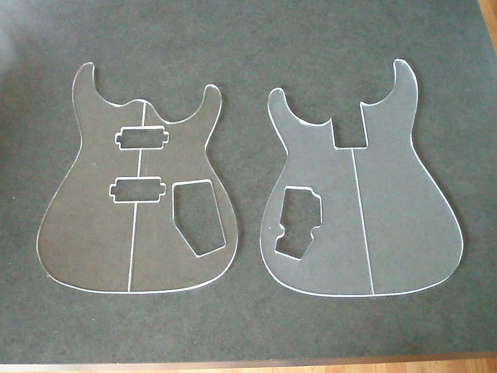
The curves on these templates were polylines. I had to turn my cut tolerance to .0001 to eliminate the faceted edge you can get cutting splines and what not. I didn't notice how many lines the program was....but it was pretty big.
-
I cut them on a CNC mill using the cad data that MzI supplied.
-
I just thought I would throw up a picture of some templates I made for a fellow memeber...MZI. They are cnc'd out of .220 thick acrylic.
-
Definitely us a drill press! Put a block of scrap wood on the back of what you are drilling...this will keep your wood from breaking out when the drill pops through.
-
Pete you're the man! Switching those wires fixed it! Thanks a million.
-
Thanks for the input guys!
If that doesn't work, don't throw it across the room.I was almost to that point Thurs afternoon...then family stuff pulled me away from what I was doing. It was probably a good thing!
When you are just testing you don't have to solder.. You can twist.So clipping things together with some alligator clips should be good for the testing phase? That would be great...I'm getting sick of desoldering, LOL.
Pete, The red and white wire on these pickups came already soldered together, so those should be right. As far as the switch goes, it is just a standard 3-way toggle (1 pos =neck, mid pos = both, 3 pos = bridge). There are 3 lugs on one side of the switch and 1 lug on the other. The 2 outside lugs on the 3 lug side of the switch are connected to the hot wires from each pickup. The center lug on that side goes to ground. The single lug on the other side of the switch goes to the volume pot. Does this sound right?
Thanks again for the help.
Jeremy
-
Nice work...I can't believe that's the same neck.
-
Wow that is green! I dig it....but it may be a little more C.C. Deville than most metal heads would admit to liking.
-
Hey John,
Here is the wiring diagram I grabbed from seymour duncan.
this diagram does not say whether the green and black wires are + or -.....so I found this page on Stew Macs website.
This says a SD humbucker is hot or + on the black wire and - on the green wire.
The sheet that came with my GFS humbuckers said that their green wire was hot and their black wire was -.
So by following the original SD diagram I had my + and - reversed. So last night I switched the greens and the blacks and I still have a wicked hum and only the faintest guitar sound. The hum gets louder and quieter when I turn the pot, but it is there no matter what switch position I use. I have everything grounded to the back of the pot.
I am at work right now so I don't have an actual picture of my wiring, but if it would help I can post one this afternoon.
I'm about ready to disconnect everything and hook each PU to the jack individually just to see if they are working and then add the switch and the pot. Any help you can throw at me would be great.
-
Yeah, I agree on that. Generally people like this is what I like the most in the metal industry. At the same time I think it is kinda weird that he could not get over whining about being kicked out of Metallica like 100 years ago. Seems weird that such a strong minded character has such problems getting over that kinda thing...
Competing with Metallica became the driving force of Mustaines life. He always seemed to be one step behind them and that bugged the hell out of him.
-
ok...well I tried switching the wires at the jack....didn't work. I tried switching all the hot and ground wires around...still buzzes like a banshee...help!
-
8. Apply amber dye
9. Apply black dye
10. Let dry, then sand down so that only the flame remains
11. Apply amber dye over maple
12. Apply red from outside towards center
13. Apply black in a similar fashion
I would be careful (experiment on scrap first) using black with amber - you can easily end up with a funky greenish tinge. Very dark tobacco brown might be a better choice.
mikhailgtrski is right....a large component of the black dye is blue. If you mix yellow or amber with it your going to end up with some sort of green. You will avoid this problem if you use a really dark brown. You would also get some funky interactions between the red and the black.
-
thanks geo...I'll give that a try. If swapping the wires at the jack doesn't work....I'll just start over.
-
I have a couple of humbuckers from GFS that I am installing in my new guitar. I used a wiring diagram from the seymour duncan site for 2 hbs with 1 vol pot and a 3 way switch. I got it all wired up and all it does is hum. So I started looking more closely and according the the diagrams on stewmacs site, on SD pickups the black wire is hot and the green is ground. According to the paper that came with the GFS pickups their green wire is hot and the black is ground. So apparently I have my hot wire and ground flipped around. Can I just switch the wiring at the input jack? Or do I have to go back and change all my black and green wires? This is what I get for assuming there was some standard color code for pickup wires

Please be gentle....I'm probably the most electronically challenged person here.
-
I'm finishing up #2 (2 or 3 more wires to solder and some nut adjustments to make). The body blank for #3 has been sitting in my shop taunting me for a while now.
-
Just get the dial ones...no batteries to die....ever!

Mixing Dyes To Acheive A Specific Color
in Inlays and Finishing Chat
Posted
I don't think there is anyway to really "copy" what you had other than a hit and miss type approach. You're probably going to need to start mixing and testing and adding a little of this and test, add a little of that then test....