


LarsXI
-
Posts
22 -
Joined
-
Last visited
Content Type
Profiles
News and Information
Tutorials
Product Reviews
Supplier Listings
Articles
Guitar Of The Month
Links and Resources
Forums
Gallery
Downloads
Posts posted by LarsXI
-
-
Phase switch? Pretty straightforward.
-
If I understand what you're trying to do, I think it should be possible with an on/off/on dpdt. Radioshack carries a mini swith like that, I believe.
The wiring itself would require wiring the two inner wires of the 4 conductor humbucker together. This is standard for the regular hum bucker series mode. You would wire the two inners from the neck pup to the middle lug on one side of the dpdt, and the two inners from the bridge would go on the other side, middle lug. Then with the remaining 4 outer lugs you would choose two diagonally opposite each other and connect them to ground (which two would determine the orientation of the switch). In the upper position, one humbucker would be tapped, the other normal. In the lower, the opposite humbucker would be tapped.
Hopefully this is what you were looking for, if you'd like me to draw it out, it wouldn't be a problem and would probably be clearer.
edit:
here we are
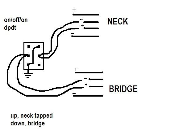
correct me if I'm wrong, I did this quickly
-
For the sake of developing an alternative to the F/R, I've searched around for info on op amp preamps and I believe I have the beginning of a workable circuit.
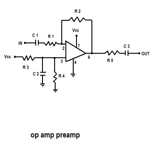
I drew this up looking at a combination of somewhat vague diagrams, so I'm not sure if this is workable? Unfortunately, I managed this from looking at a couple of vague, non-guitar related projects, so I'm unsure about what op amp to use, or even what values the resistors and caps should be at. Apparently R2/R1 will determine gain, which I believe we want relatively high?
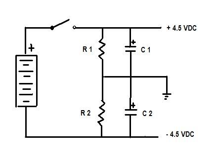
The part I'm having trouble with is powering the thing. R3 and R4 are intended to be equal and allow for the use of a single power source. However, this aspect is absent from the schematics of various amps and preamp amp combinations I've seen so far. Is this normally done with an ensemble like this http://i278.photobucket.com/albums/kk83/La...powersupply.jpg ? How would that then be used on this preamp and/or amps like this one?
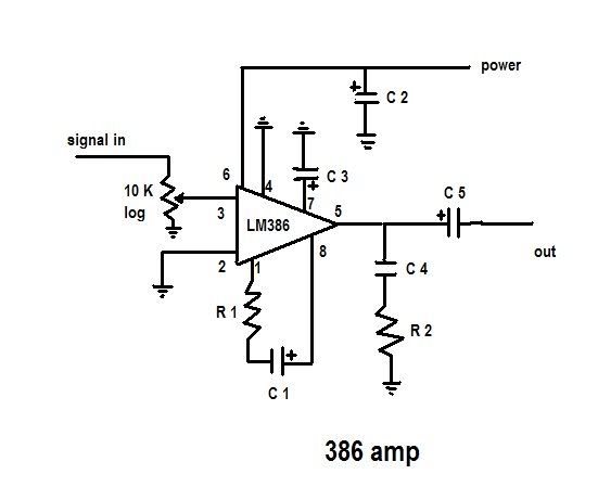
I redrew the schematic for an amp referred to as the "champ" earlier in this thread. It appears similiar to the little gem and seems to have some of the modifications that were mentioned.
R1 1k
R2 10ohms
not completely sure of those
C1 10
C2 100
C3 10
C4 0.1
C5 200
These look like they're all in uF
The pot at the beginning may or may not be necessary.
C5 could perhaps be replaced with a 100 uF
Unfortunately, I've found little info on op amp preamps specifically for guitar. Thus, I'm unable to develop it any further than this until I have an idea about which components and such I should shoot for.
Hopefully I'll be able to refine this to the point where we have a circuit to compete with the F/R. It seems there's a need for a new universal setup.
-
Ah. The impedance stuff has really been tripping me up today. I'm sorry for bothering you with it, and I'm very grateful.
I'm going to try various FET based circuits, and I'll be more than happy to share once I get something working well. So far, a lot of DIY piezo ideas for basses are floating around, but guitar piezo designs tend to be for acoustics without any magnetic pickups.
hopefully I'll have something in the next couple of days.
Thanks again
-
I'm making a dirt cheap radio shack piezo pickup for my dirt cheap strat copy. I've been searching for a buffer circuit that I can make so I can blend the piezo with a single 6.5ohm pickup without impedance problems. I've found several potential schematics, but I'm unsure if they'll serve the purpose.
One of them:
http://www.till.com/articles/GuitarPreamp/
Another:
http://www.cafewalter.com/cafewalter/fetpre/pzp1_project.htm
Ideally, I'd like to be able to blend the piezo signal and the magnetic signal with a 500k blend pot I have on hand.
Any insight would be greatly appreciated,
Thanks for your time
-
Hello again, I'm about to experiment with this concept a bit, and I'm afraid I'm a bit curious about the preamp and LM386 amp deal.
This should be a quote. I found it in the thread as a quote itself, however, I couldn't find the original post and I have no idea about the context.
the link should be http://www.national.com/ds/LM/LM386.pdf
For instance, the LM386 Data Sheet LINK, page 5 top right x200 circuit, suggests a 10uF cap between pins 1 and 8 (you can leave the trim pot in by connecting the cap to the trim and the trim to the other pin for adjustable gain) which helps with oscillation, the "zobel network" is the small cap and resistor from pin 5 (your C1 connection) to ground. This is also there to help with stability and in this high gain application, the circuit needs all the help it can get. As for the "Fetzer" J201 part of the circuit, this is not something I am familiar with myself. You may wish to substitute the output cap (your C1) for something smaller, I use a 100uF to get a kind of mixed mode and enhanced harmonics.
The circuit that is referenced there, including the recommended modifications, does that included just one part of the preamp and LM386 package, or will that work to drive a unit? I must apologize for my lack of understanding of this part of the system.
-
I'm looking for an auto-wah/envelope filter pedal. At this point, the Boss AW-3 looks good, but supposedly the humanizer mode adds some unwanted distortion. The humanizer is something I'd like, and the pedal overall seems like a good value. It'll work with a bass as well, which I think is important. Any thoughts on the distortion issue?
-
For those with a bigsby tailpeice on a string-through guitar, have you ever tried only stringing some of the strings through the bigsby and the others regular? It could lead to some interesting possibilities, with drone notes and simultaneous flutters.
I've been playing with the idea of modifying a bigsby quite extensively using a thicker rod (where the string mount), a gear ratio and different spring set-ups. In my mind, the bigsby would have a lot of potential if it weren't for the limited range.
-
Yeah, I'm thinking dummy coil at this point as well. The coil would be only slightly more difficult to obtain and install than a cap.
-
The clicks aren't just the waveform clipping, right?
Although it doesn't sound like thats your problem if the click becomes less noticeable on subsequent presses.
-
I wonder what a very large capacitor would do for us. Such that the cutoff point would effectively kill all audible tone. I have no idea if this would cut off the hum as well, but if something like a dummy coil works, who knows?
-
yeah, I was beginning to think of doing it that way. I should have an extra p90 to experiment with, so in the end, it may be similiar to the blueshawk.
Thanks for your help
-
Hmm, thanks for the lead, I'll put some research into the dummy coils.
For my project specifically, I'll have a single coil neck and humbucker bridge. I was hoping to work some switching that would use one of the two humbucker coils in this method. I'll have to do some experimentation.
-
Would it be possible to run a strat 2/4 position and put a cap on the middle pickup that bleeds off all audible tone except for stuff around the 60 cycle? Thus obtaining the neck/bridge pickup alone but still with hum-canceling benefits?
It seems that this would have been done before if it was possible.
-
Ah, thanks. That topic was relatively recent, I seem to have not searched rigorously enough.
Thats sound reasoning. I'll probably avoid finishing inside.
-
For those with semi-hollow guitars with soundholes, do you apply anything to the inside of the guitar for durability/weathering purposes? I'm guessing its fine to leave it unfinished. However, does it make sense to seal it to avoid humidity issues on the world tour?
-
Has anyone had experience with wiring pickups with separate volume pots in series? For example, having two single coils with separate volumes and a switch for series operation. When in series, do the volumes act differently/ not function?
A future build will include a lot of complex alternating series/parallel modes and I do not know enough about series operation at this point.
-
The piggyback method mentioned sounds like a good move. I have a p90 in the neck, I'll find a cheap one to experiment on. Eventually, should I shoot for an additional coil on top of the pickup coil, but in the same housing?
-
Is it possible to use the signal from a piezo pickup to drive a sustainer system? If this is the case, would it make sense to use a low-profile piezo pickup along with a mid position driver in a sustainer system that is independent of the regular magnetic pickups? In that case, the normal pickups would operate normally and the sustainer circuitry would be completely separate. The sound of the piezo itself would not be sent through to the amp at all. It seems that this would offer an advantage in that the sustainer would be solely for the purpose of continuous string vibration.
Or is this a bit far-fetched? I am largely ignorant of the theory involved, but reading over the last couple pages of the thread, this is what I've come up with.
-
Ah, thank you kindly.
-
I've searched extensively for measurements to make a trem template, and there are three measurements I haven't been able to find anywhere. I need to know the length of the entire back cavity, from the edge closest to the neck to the far edge. Also, I need to know the width of the chamber in which the sustain block is located. Finally, I need to know the alignment of the spring chamber relative to the the sustain block route. Knowing the distance from the right or left edge of the spring chamber to the right/left edge of the block route would be sufficient.
.........................................................______......__
.........................................................l....|.....l......|
.........................................................l...C.....l......|
.____________________________l.._|_....l.....|
l....................................................................l.....|
l....................................................................l.....|
l....................................................................l.....B
l.<-----------...A....------------------------------>..l.....|
l....................................................................l.....|
l.____________________________...........l.....|
..........................................................l.___._.l..._|_
If anyone has insight to offer, it would be appreciated.
Trem Questions
in Solidbody Guitar and Bass Chat
Posted
I was thinking about modifying a Bigsby a couple months ago. I thought about using a torsion spring or two. It would be interesting to try one on each side of the bar. Also, I thought about actually increasing the diameter of the bar thinking that this would allow more movement and thus more pitch range. Finally, I had vague thoughts about changing the arm/lever itself into one that used a simple gear ratio for better movement. Unfortunately, I didn't actually try any of this. But hey, food for thought.