


darqdean
-
Posts
5 -
Joined
-
Last visited
Content Type
Profiles
News and Information
Tutorials
Product Reviews
Supplier Listings
Articles
Guitar Of The Month
Links and Resources
Forums
Gallery
Downloads
Posts posted by darqdean
-
-
If only you were here a lot earlier to point this out, this avenue could have been explored a little further. So, here is your chance, hook both the pickup and the driver coils in parallel and post your readings and results comparing the driver alone and the pickup/driver in parallel (definitely not series). It could even help with the switching woes. A whole area there to explore with a very simple connection of wires...
Well spotted...welcome aboard... pete
Well, it worked
 thanks for the suggestion
 With just the driver connected I managed to measure about 80v pk-pk on the pickup winding, which was then picked-up by middle pickup and caused some really nasty and undesirable HF squealing. I connected it in parallel with the drive winding and low and behold everything was under control
I've fitted a 4p2t switch (available >|here|< ) so that when I switch the sustainer circuit on the neck pickup winding is connected in parallel with the driver and in the "off" position it behaves like a standard pickup.I also fitted some magnetic screening to the driver/pickup by wrapping a thin strip of steel three-quarters of the way around the bobbin, wrapping that in tape and then fitting a shorter piece to cover the gap. It is important that this screen does not go all the way around the bobbin and make a complete circuit as this will result in heavy currents being induced in it from the driver coil, which will serverely over-load the drive-amp. Connecting both these plates to signal ground also provides some electrical screening. Now if I set the drive to maximum and damp the strings I get zero feedback through any electro-magnetic coupling to the middle pickup - remove the damping and the strings sustain nicely.
-
Well.. the amp ain't working.
Will try to poll-twist some of the capacitors, think it could be one of them.
I can see at pictures of other Ruby's, that the 100uF capacitor on pin 7, is a ceramic type. The one I use is a electrolytic.
Not sure if that would do any different?
The value of the cap on pin 7 will not stop the device working - it is only a supply filter for the I/P stage of the amplifier to prevent the output from affecting the input through the supply line. The ceramic type you have seen in the "standard" Ruby is 100nF, not 100uF (a 100uF ceramic would be as big as a car!) - in principle the larger the value the better.
It will work without a capacitor fitted to pin-7 so if you suspect this cap then remove it.
The same is true with the R-C network between pins 1 and 8 - the circuit will work without these, so if the amp still isn't working, unsolder one of these components.
hope this helps...
-
::snip::
If only you were here a lot earlier to point this out, this avenue could have been explored a little further. So, here is your chance, hook both the pickup and the driver coils in parallel and post your readings and results comparing the driver alone and the pickup/driver in parallel (definitely not series). It could even help with the switching woes. A whole area there to explore with a very simple connection of wires...
Well spotted...welcome aboard... pete
Thanks for the welcome pete.
Yes, I am a bit of a johnny-come-lately here - I've worked my way through several pages of the thread but alas not all.
I'll try the parallel connection - I never thought of that, I was just going to ground both ends of the coil and hope that the resulting low current loop didn't cause too many problems, using the driver cct as a low-impedance load will do the same thing - it should certainly tidy-up some of the stray noise/feedback issues. An open-circuit secondary coil can result in core saturation if the primary is driven too hard, but I think (hope) you'd have to drive it really hard for that to be a problem here.
As an aside, I'm currently using the trusted LM386 amplifier to drive it, but I am also developing a Class-D amplifier (kind of inspired by the sustainiac patent - but without the deliberate errors
) - the prototype works okay on the bench, but it's too big to fit inside a guitar cavity - I'm going to investigate using a switch-mode psu control chip for this sometime, (circuit-wise it's basically the same thing), which will drastically reduce the cct board size. If it works I'll post it here.dean©
-
I'm currently mid-way through building my own sustainer and have a general question for anyone who's built a twin driver/pickup, like this one from psw's tutorial:
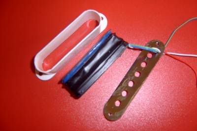
This is effectively a transformer with the (blue) driver being the primary and the (black) pickup the secondary. The turns-ratio for this is high, (in the version I have built it's about 1:36), so an 8v pk-pk drive signal will induce hundreds of volts in the secondary (
) - which in turn will cause all kinds of interference issues with the other pickups on the guitar whether the neck-pickup is switched in or not.Is this a problem? Has anyone addressed/fix this in the past?
 thanks for the suggestion
Sustainer Ideas
in Electronics Chat
Posted
If I may interject my two cents worth...
The 'problem' of filters is that they are fixed frequency, so they only work for a narrow range of notes - a filter that emphasises the harmonics of one note will not work for notes that are an octave or two either side of that - it isn't possible to design a filter that would work across the entire range of the guitar since the harmonics of one note are the fundamentals of others. The other issue with them is that they phase shift by different degrees for different frequencies, thus affecting which harmonics the driver is trying to boost.
The 'simple' mechanical phase-shift switch overcomes all these problems since it uses the string itself as the 'active' frequency dependant component - the string can only vibrate at harmonics of the fundamental note and the driver can only drive the string at harmonic anti-modes, so regardless of which note is being played, the driver will always try and supress the fundamental note and boost the harmonics.
One way to achieve a 'blend' would be to mix the output of the bridge pickup with the inverted signal from the middle pickup - this would effectively suppress the fundametal note while allowing the harmonic difference between the two pickups through.
pete: if you email me your digital switching problem I could see if I can come-up with a solution for you.
dean©