


space_ryerson
-
Posts
19 -
Joined
-
Last visited
Content Type
Profiles
News and Information
Tutorials
Product Reviews
Supplier Listings
Articles
Guitar Of The Month
Links and Resources
Forums
Gallery
Downloads
Posts posted by space_ryerson
-
-
Those are some very inspiring demoes McSeem! Some of the demoes have a nice synth-like quality. Definitely keep us posted on your progress.
-
I should mention that Guitar Fetish has a delay MODboard that can be installed directly into a guitar. I'm more of a pedal guy, but it could be fun to have a delay built into a guitar.
-
ryerson- the chip says Jrc with the numbers 2073C above jrc and 5075G below it sorry for any confusion.
No worries
 Thanks for the info.
 -
the coil measures at seven ohms and the chip is a 2073
Thanks! I'm guessing that's a NJM2073?
-
Interesting. I'm glad that it works for you! Out of curiosity, what chip(s) are on the board for this amp?
-
I've got a micro kill switch on two of my guitars as well. I wish they had a shorter 'throw', in that it was a shorter distance to press down before it latches, so I can do the kill-switch thing faster. I've been meaning to take one of the switches apart to see if I can mod it to do that. I've also thought about using old game controller buttons for kill-switches, since they are meant to be pressed very fast.
-
Good news Paul! May your sustain last longer than the arguments about it on this forum!
-
In the effects pedal work I've done, normally to power a LED, I connect the 9V+ from the battery, then use a resistor to take the voltage down to 1.3V-1.8Vish. Different LEDs have slightly different voltage and current requirements, and you can adjust the brightness by the amount of voltage applied to them. I've never worked with several LED's in a row, but if you only want to use one resistor, then the LED's will have to be wired in a series. Here's a site that has a lot of info. Also, try Googling "LED resistor calculator", since there are a lot of sites that do just that. Also, I don't know why you would need a driver.
Hope this helps.
-
I like the way you're thinking Hank! I was actually contemplating either an Arduino or DSP based AGC/lag circuit recently, in a similar line of thinking. I look forward to hearing how it works out.
-
space, could you go to the final frontier & clarify which schematic you posted a couple of pages back please?
It's the Floyd Rose sustainer
I don't know nearly as much about the Fernandes sustainer. After a lot of number crunching I *think* I've found a suitable transformer replacement, which I'll be ordering from Mouser tonight. This thread was a really informative read. As for the part numbers I gave you earlier, I was only able to read Q9, and not Q8, due to how they are pressed together; but they looked identical.
-
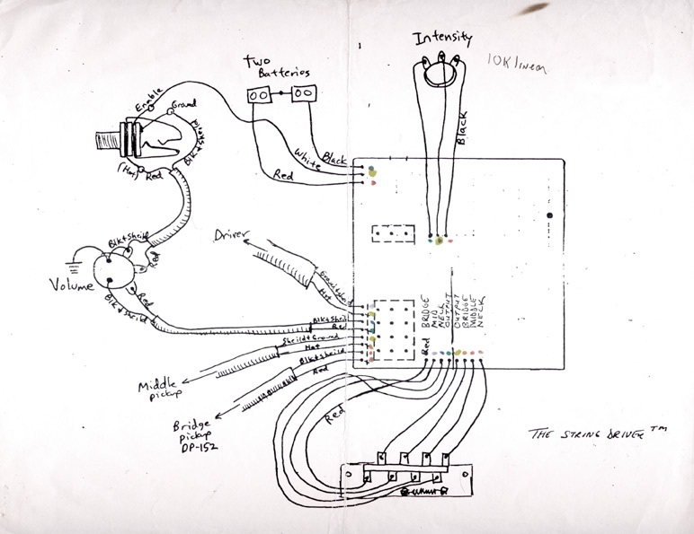
That's a great little schematic (but it looks like it was drawn by someone with a crayon!). I'd love to have had some readings for the associated driver coil ...inductcance, DC resistance, wire gauge etc. (DC resistance would be a start....do you have a way of measuring this space_ryerson)
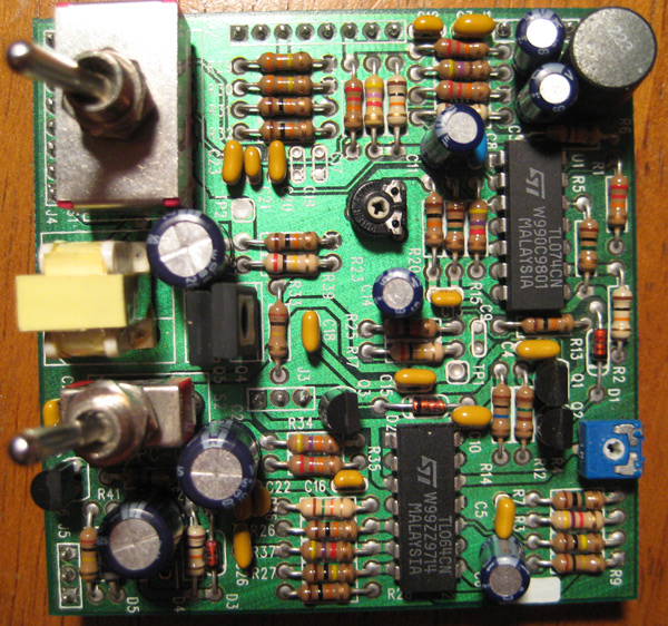
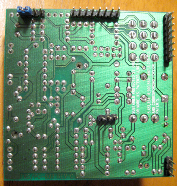
Crayon indeed! The DC resistance of the driver is only 9.8 ohms! How do I test inductance? I'm not taking the driver apart, since I don't want to jeopardize it working, but there is some info on windings, etc. in patent 5,123,324. In a prior post in this thread I took shots of both sides of the circuit board, which may be of some help
Excellent...just found it http://www.tinyurl.com/clbrhu (I can see they've used a TL074 for U1 & a TL064 for U2)...I can't make out the power transistors Q9 & Q10 though (it'd be helpful if you could eyeball their casings to see what characters they have on them)
Since the transformer doesn't work now anyway, if push comes to shove, you could always desolder it & on the damaged side start unwinding it (presumably one side's coil is reading open/short circuit), - keeping a count of the number of windings get a micrometer to establish the wire gauge ....once you have the number of windings & the gauge info to hand - rewind it with replacement wire! Don't laugh, my wife used to do this for a living...& it's as low tech as that!
Hey Hank, I had a gander, and Q9 & Q10 on that diagram are Motorola 731 JE172's. I don't know if there is any difference between them and a MJE172. Moving along, I only recognize some of the FETs on the board. There are two '271 p824cf's, one 2n3904a, and one 'P 6241f'.
-
That's not a bad idea. I'm definitely driven enough to sit down and count windings
The only trouble is that I can't seem to figure out how to take the transformer apart. I'll take some pics when I get home tonight. I'll also look up what Q9 and Q10 are for you.
-
That's a great little schematic (but it looks like it was drawn by someone with a crayon!). I'd love to have had some readings for the associated driver coil ...inductcance, DC resistance, wire gauge etc. (DC resistance would be a start....do you have a way of measuring this space_ryerson)
Crayon indeed! The DC resistance of the driver is only 9.8 ohms! How do I test inductance? I'm not taking the driver apart, since I don't want to jeopardize it working, but there is some info on windings, etc. in patent 5,123,324. In a prior post in this thread I took shots of both sides of the circuit board, which may be of some help. Also, the driver has a metal shield on the side facing the bridge of the guitar, which I feel is there to shield the rest of the guitar from EMI.
Ok, here's my take -the transformer 'T1' is *only* used to crank up the driver coil signal level it can also be utilised as a traditional magnetic pickup - it's not used in the sustaining aspect of the circuit at all. Therefore if you're saying your sustainer doesn't work because of transformer 'T1' being faulty - then T1 is *not* your problem...ie you have a fault elsewhere. If you're saying your system doesn't work with the driver being used as a traditional guitar pickup coil...then yes, space_ryerson, you'll need a 25:1 step up transformer (that said, if it's also not sustaining too, it'll likely be be the driver coil - have you have done a DC resisiatnce check?).You are 100% correct. The sustainer portion works just fine (great, in fact!) without the transformer, but when the circuit is off, the neck pickup isn't functioning. I can tell the transformer is visually damaged, so I'm just trying to find a replacement, but not having much luck.
Reading the scanned patents in google patents for this, namely 4,907,483 and 5,123,324, really illuminated to me how the Floyd Rose Sustainer works. It's dense reading, but explains why they chose to use quad op amps, etc. The phase lag sections, and how harmonic mode is achieved were also very intriguing.
-
Hi PSW, remember me? I'm the one with the dead yellow transformer on a Floyd Rose Sustainer. Well, I've found out quite a bit more, but could still use some help finding a replacement transformer. After months of sleuthing, a very nice guy on another forum took apart his Jackson PC-1 for me, and told me this was written on the transformer:
C9219-A
0543
Seems promising, but after a lot of googling, I couldn't find any info. So, I went and read all of the patents printed on the circuit board (4,907,483/ 5,123,324/ 5,200,569/ 5,233123), which yielded this:
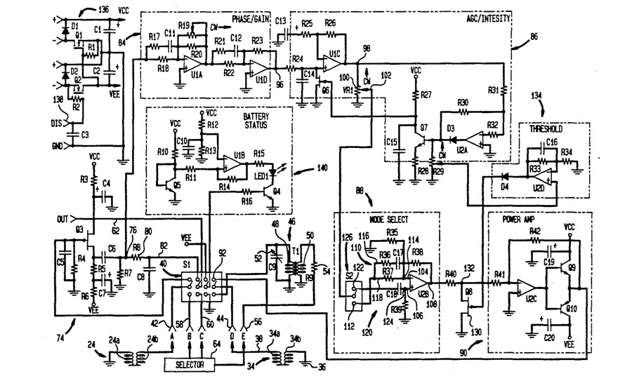
Pretty interesting, eh? The mystery transformer is marked as T1. I went and looked at the circuit board, and c9 is 100nf, and r9 is 10k. The sustainer driver/pickup is 34 in the diagram (9.8 ohms in my guitar), and the bridge pickup is 24 (15.4k, also in my guitar). This at least showed me what was going on in the circuit, but I was still unclear, until I read this in patent 5,123,324:
Although the pickup coil (of the sustainer driver) provides relatively low voltage signals, these voltages are stepped up by the transformer, so that the system provides output voltages comparable to those achieved with conventional high inductance pickups. This arrangement provides significant cost and performance benefits.Makes sense, and then there's this:
(The) transformer is a low-noise transformer such as a nickel core transformer. Transformer may be an autotransformer in which the primary and secondary coils are parts of the same winding. Transformer may be arrange to provide a step up voltage ration of about 15:1 to about 30:1, preferably about 20:1 to about 25:1. Transformer is disposed in relatively close proximity to neck pickup, hence to the coil system thereof.Ok, now I'm much closer, but I don't know where to find a transformer in this ratio range. I went through all of mouser, and couldn't find anything that fit the bill. Any suggestions?
There's a lot more about what the transformer does in patent 5,123,324, and a lot of interesting info about the harmonic mode in patent 4,907,483.
Any help you guys can give to aid me in finding a replacement transformer would be great!
-
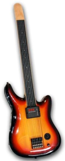
I did an image search for starr labs and this came up.
That's their ZTar, or whatever it's called. Starr Labs sells a drop-in replacement pickup switch to replace a standard 5-way, but has either 3 or 4 LED buttons that lit up when selected. The current price list has them at $50 for the 3 button, and $75 for the 4 button switch. I still have an old catalog of theirs somewhere in my parent's house. After some googling, I found some pictures. If you look at the blue guitar here, you can see the 3-button version. It probably just utilizes some logic switch chip, and could be DIY'ed, but it's out of my current grasp.
-
I think I get what you mean. Back in the 90's there was a pickup switch by Starr Labs, which is similar to the type of switching you describe. There aren't any pictures, but here's some info. I wish I could find you a photo, because it was pretty decent looking. Also, Jerry Garcia actually buffered his effects through his guitar, and was able to switch them on and off via his guitar. There's some info here, including a wiring diagram.
-
Sorry to hear that you aren't feeling the best, PSW. I'm glad you are reaching the end of the battle though!
I did PM captainstrat back around March, but he never replied, and stopped posting. I may try again. The interesting part about the transformer is that absolutely no sound comes out of the neck pickup, so I would venture a guess that it's doing some form of rectification. Also, the driver has a large metal shield on the side facing the bridge; presumably to shield from noise. Not only is this design 18V, but it eats batteries relatively quickly. I've been contemplating moving over to a rechargeable scenario for that. Also of interest, while the sustainer is on, when I change the settings of the pickup switch, the sound does change; but not so much like changing pickups. There is a point in one of the patents I mention that does talk about transformer, but it has been a long time since I've sat and read it all. I know it doesn't mention that value of said transformer.
-
Hi everyone,
I've been reading this massive sustainer thread on and off for a few years now. I was bit with the sustainer bug back in the 90's, and tried to get a guitar with one in it. Being left-handed, that was not easy. Very long story short, I managed to buy a floyd rose sustainer system brand new, and built a guitar to put it in. All went well, but the neck pickup/sustainer driver wouldn't work as a normal pickup when the sustainer was off. I lived with this for a while, and eventually I contacted Floyd Rose. They put me in touch with Rick Knotts, who was the primary person developing the Floyd sustainer, and primary patent holder. Among other info (like how to calibrate it), he said my problem was with the transformer (so that's what it does!), and if re-orienting it didn't fix the problem (it didn't) he would mail me replacement one if I liked. The transformer on the circuit board didn't have any markings on it, so I couldn't just order another one from Mouser or whomever. I then tried to get back in touch with him, but according to floyd rose, he left the company to go on tour again with his band, and took all of the technical info for the sustainer and patents with him! I tried chasing him down, but no luck.
Which leads me here. I'm desperately trying to figure out the value of the transformer, and hope maybe one of you knows this. Captain Strat posted a photo of a nearly identical circuit board, with the transformer markings, but it was too small to read. Doh! So, if anyone knows the value of that transformer, I'd be infinitely grateful for that info! This is the same sustainer as the ones in Jackson guitars (such as the Phil Collen model) and the newer Kramer sustainers. I really like how nicely the Floyd sustainer works, and would be even happier if the neck pickup worked!
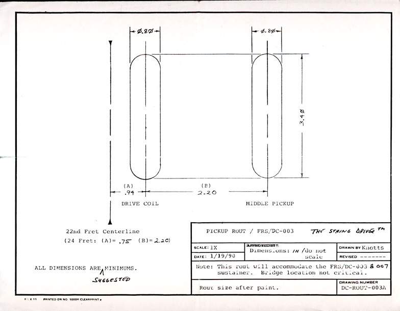
Since you all are sustainer nuts, I figure you'd like some of these photos and text about the Floyd Rose Sustainer:
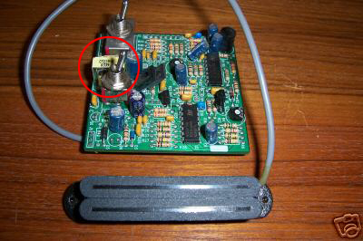
Here's the top and bottom of the circuit board (the faulty transformer is yellow, on the left):
Here's CaptainStrat's photo of the similar board:
Here's the wiring diagram that was provided (hand drawn):
Here's some info on calibration that Rick provided:
The four pins not specified in the diagram: For changing the load on the bridge pickup. The difference is subtle. Check the sound of the bridge pickup with sustainer switched on and then off. Use the guitar chord you would normally use. If the sound is very close to the same, you can ignore the pins. If you hear a difference not to your liking, try jumping 1 and 2 or 3 and 4 (numbered consecutively).The trim pots: One is for sensitivity and the other is for output. Turn the
output and sensitivity all the way up, then back off until the uncontrolled
feedback ceases. You will then have the highest possible output. You then
back the sensitivity down to whatever level you prefer based on touch.
Set the height of the driver as close to the strings as you can for the
best driver performance.
I've posted some more info with these links:
Kramer's 80's sustainer manual
PSW, I'm definitely interested in one of your sustainers when you make one commercially available! Again, if any of you know the value of that transformer, let me know!
 Thanks for the info.
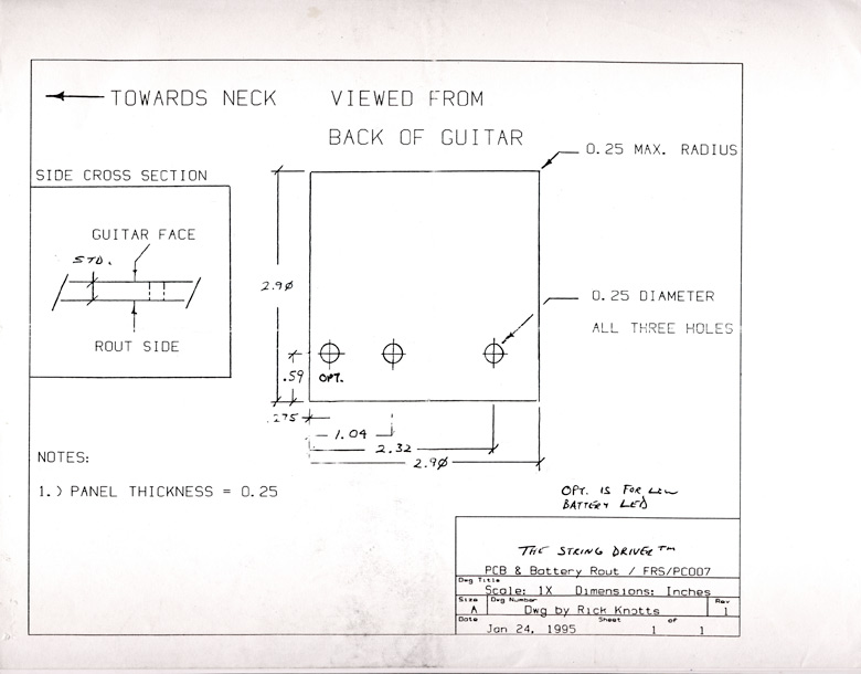
Midi Footswitch
in Electronics Chat
Posted
Does this fit your bill?