


Strib
-
Posts
5 -
Joined
-
Last visited
Content Type
Profiles
News and Information
Tutorials
Product Reviews
Supplier Listings
Articles
Guitar Of The Month
Links and Resources
Forums
Gallery
Downloads
Posts posted by Strib
-
-
Hi there !
Tests passed successfuly

I've built 2 preamp/opamp to do my tests :
- first fetzer ruby, which was not loud enough, because of the lm386 N1 chip (only 0.7w).
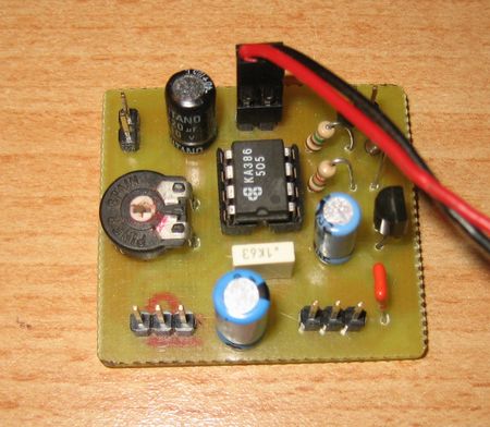
As I was almost sure about the driver, then, I managed to build another amp, based on a LM741 preamp and a TBA820M opamp.
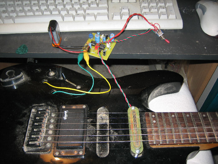
The difference between the 2 circuits is very important, with only one pot for the gain, here it is :
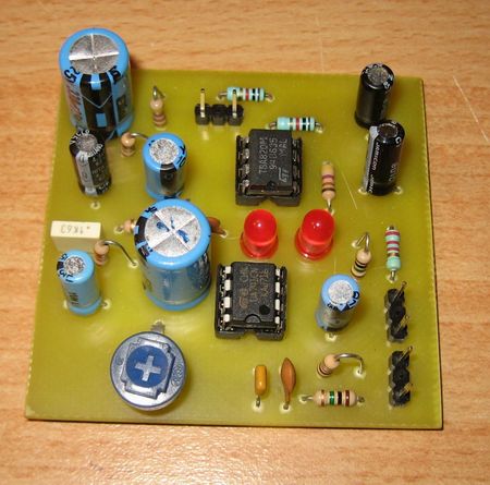
This is a prototype, I've now reduced the size of the PCB to 5cmx3cm . That will allow me to install it directly into electronic cavity.
I've built 2 differents drivers, the first one with a piece of planer blade, 2.5mm thick :
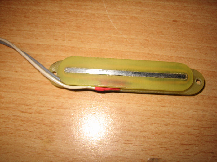
The second, made from transformer scratched :
I first ued a ceramic bar from an old single coil, but the sustain was not very accurate, especially on the G/E/B strings (because of the diameter of the chords), then I replaced the bar with small square neodymium magnets (6mmx4mm 2mm thick), and this solved the problem.
My old rusty guitar is now ready to cry :
Here are 2 divs movies during first tests :
Sustain forever

Cheers,
Strib
-
Winding a custom pickup is a bit of an adventure. You may wish to consider modifying a pre-wound cheap pickup. This tends to be cheaper and easier than making your own...unless you are pretty experienced in doing this already. Making pickups is a whole other project in itself.
Hello pete, thanks a lot for your quick response. I know that i'm on the right start, I'll be back with more experiment.
I use tu wind my own pickups as I make my own guitars (you can have a look here : www.strib.fr )
Thanks again and, see you as soon as possible
Strib
-
Ok...with the F/R...have a look a page back or so about my mods and risingforce's attempt to do a layout of them for the F/R...perhaps it needs another name!
The signal goes from the bridge pickup to the input of the circuit and then onto the switching and controls. Not through the circuit, but both attached to the input of the circuit, only the driver goes to the output. There are variations to get the same effective wiring and it would appear that you have got that bit right!
Ok pete, but what is disturbing me is that the original bridge signal is splitted in 2 parts and go to the F/R input AND the guitar controls (I consider this wiring in "paralel").
Have a look at my scheme (Based on a typical wiring diagram from SD) :
In this case : is the signal of the bridge pickup divided ?
Most likely however, you haven't said what kind of circuit you are using and the kind of thing you are describing sounds like "loading effects". If the circuit you are using expects a line signal, and you send a guitar into it, the "impedance" will be all wrong. An MP3 player might work, or computer, because these have preamps in them to boost the signal to the correct impedance, a normal guitar does not. Worse, if you try and share the signal between the circuit and another amp like a guitar amp...the tone and everything suffers greatly and the performance of the sustainer effected too. It might work a bit, but not as well as you might hope. In the F/R, the fetzer transistor stage allows for a huge range of signals preventing the signal from getting "loaded down" and optimising the signal for the "poweramp LM386" stage (which does most of the work).So, if it is working 'kind of', this may be so, but it will work even better without the loss of tone with a proper circuit. So, extremely well done and it sounds as if you have taken all my recent advice and taken it in stages and prepared to redo the driver if necessary...congratulations.
You pointed it !
I used a little guitar amp to do the job, but i know that I have to make the F/R soon (I'm waiting for some components right now) for improving my tests;
When I told you that I have larsen and EMI, I had only the bridge pickup and the center single coil on the guitar. Neck pickup has been replaced by the driver.
BTW, I plan to wind a special pickup like yours, which will have a typical 0.063mm (AWG42) wiring for the passive pickup stage, and a special stage above with 0.2mm wire for the driver, but it'll be another story !
Best regards
Strib
-
Hi there,
I'm glad to join, many years after, this sustainer topic, and - first of all - i would thank every contributor for all the usefull informations we can find in this thread.
I'm, at this point, building my own (already build my first driver prototype) made from some material i've canibalized from an old transformer (0.2mm wire), an old planer blade (core driver) some epoxy PCB and a ceramic magnet found on the back of an old pickup.
I'm planing to build the F/R amp these days, but I did some tests with an external amplifier wich allowed me to have some sustain (fondamental and harmonical) on some open chords : Great start...
I think I have to reduce the core height (mine is 5mm) to the ideal size defined by the psw's tests, and fine tune the position of the driver for the moment, there is a little thing I can't understand (even if I've searched for it in the entire thread ...) :
How are connected the pickup wires which are supposed to be connected to the onboard guitar circuit AND to the F/R amp input ?
I've picked the wires directly from the pots connections, but the signal (ie the final sound) of the humbucker i used, seems to be altered when sustainer is on. I have a totaly different attack, and weird sound.
Thanks a lot for your help and cheers from Corsica
strib


Sustainer Ideas
in Electronics Chat
Posted · Edited by Strib
Hello !
Thanks pete
Of course I'm ready to share. The opamp/preamp come from the bobblick pages, he has developped this shematic
(It can be publied in DIY projects, I've contacted him for the autorisation, that he nicely gave me. I thank him again)
Then, I took the typical application of the TBA820M included in the datasheet :
For making these schematics and PCB :
http://www.strib.fr/images/sustainer/PCB/schema.gif
http://www.strib.fr/images/sustainer/PCB/implant.gif
http://www.strib.fr/images/sustainer/PCB/typon.gif
(these are optimized for fitting into electronic cavity. This is the same circtuit you can view in my last post. => 400DPI images, print them at 25% scale)
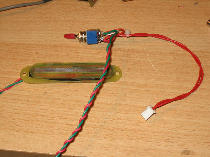
There is no more magnetic with the little neodymium, just a balanced magnetization of the bar. I've put 2 little magnets for the E/A/D strings, and 3 for the G/B/E .
The leds are supposed to act as clip as you said. The problem I have, is that I must decrease the gain for harmonic mode, because I have an EMI noise if I switch with the same level than fondamental mode...
Must solve this with a larger pot I think.
I'll try to developp a little bit more the system this week end, before thinking about finishing the installation
If you need more informations, feel free to contact me
Strib