


AndrewCE
-
Posts
121 -
Joined
-
Last visited
Content Type
Profiles
News and Information
Tutorials
Product Reviews
Supplier Listings
Articles
Guitar Of The Month
Links and Resources
Forums
Gallery
Downloads
Posts posted by AndrewCE
-
-
Yep, you're right, I missed that point. It sounds as though with a lower than matched output impedence, some power is lost. This would make sense why when I built the 18V version it sounded much better than the 9V version if it was because it was able to supply more power and make up for what was being lost. I did not measure the output current.
I found a thread where someone with a similar set of circumstances found a secondary buffer on the ouptut makes a positive impact.
http://www.electro-tech-online.com/electro...dphone-amp.html
thanks, but i dont think I'm quite ready to deal with transistors yet. i know how they work, but to actually see them implemented in a circuit spins my head around. (maybe you could refer me to a good site/article on transistor tips and how to read transistor schems?)
by the way, i have an updated schem, now with an LED and switch. Also, i fixed the wall-wart power supply problem.
unfortunately i think radio shack STOPPED stocking and selling op amp sockets, and my town only has one other electronics store (which doesnt stock them) so i seem to be at a dead end as far as soldering up a board goes.
-
If the wiper to track goes open circuit the resistance will go to infinity (theoretically) This could be a bad thing depending on circuit design. For example in radio type circuits you now have an antennae waiting to pick up noise.
If the one end is connected the highest possible value will be whatever the track is and no (or minimal) possibility of an open circuit.
Keith
oh that makes sense. thanks, keith.
-
It seems that a pot configured as a simple variable resistor would be configured: one lead at the end of the resistance track, and the other on the wiper (opposite end of the wiper left open) . But I have seen in many schematics that the 3rd prong of the pot is to be connected to the wiper. Does this matter? theoretically the resistance is the same between the two configs at all parts of the rotation. Does this reduce scratchiness or something?
-
Oh well. I'm sure all of this has been a learning experience for you to say the least. You and I are on much the same path and so I can identify with your interest, enthusiasm, confusion, disappointment, etc. No worries though, let's look at it as "right of passage".

A low impedence output can handle going into a higher impedence input, but not the other way around. This is what I've learned, but it is 2nd hand knowledge from a member of the nerd herd at my employer and other threads within this and other electronics forums, for a basic bit of evidence, it's stated about 2/3 down this page... http://www.kpsec.freeuk.com/imped.htm
In practical termns, if you think about how things like op amp based stomp boxes work, they are always very low output impedence and very high input impedence (this is why they're used as buffers and how they avoid "loading" the guitar circuit). They have no issues interfacing with the input of a guitar amp. If there is any issue with a low output impedence, then I'd also like to know why.
Impedence is not so easily measured. It's a combination of resistance, inductance, capacitance, reactance (variation with frequency), all brought together. You would need an LCR meter to measure the individual values and use some math (that I'v enot ventured to fully understand) to come up with the impedence value. I also believe there is a difference powered vs unpowered. However, I believe that for the most part, with something as simple as headphones, you can factor it down to an estimate, based on only the resistance of the headphones. I think your biggest issue is going to be the output current, not impedence. Like I said a few posts back, I hooked this up with a TL082 driving my Bose headphones (quite high output) using dual 9V supplies and it was very nice. I do not think the dual 9V supplies change the output impedence, but the output current of the op amp does go up with increased voltage supplied to the op amp.
Some of your questions are very valid and I'm not sure you're going to get the answers you really need here... notice no one else seems to be chiming in?
I would recommend joining the forums at www.allaboutcircuits.com. They have a subforum ccalled "projects" and some serious nerds there that will guaranteed be able to answer your questions better than me if not fully to your satisfaction. They have helped me out recently when I was very frustrated with a project of my own and I personally will go there first for any electronics questions after that experience.
yes, i've read many articles like this before, and the "low output impedance, high input impedance" system is the best for stompbox-to-stompbox, or from guitar to amp, etc etc, but like the article says, when driving speakers you need a matched impedance for maximum power transfer. i'm sure the concept applies when driving a 0.3" speaker just the same
as when driving a 12".
-
what 'unit'? you mean a stompbox? how does that make your amp more portable? is your amp battery powered?
i would normally have the headphone amp at the end of my pedalboard. then, i would unplug it, thus switching into battery-power mode, and velcro it to my guitar strap. at that point i would have no FX, just guitar -> patch cable -> headphone amp -> headphones. that's ultimate portability.
or, if i want, i can build the headphone amp INTO my guitar, add a headphone out jack, and only use the 9v power supply to recharge the internal battery w/o removal
-
Yes, I agree on using sockets, but why can't you just remove the chip and try replacing it? No matter what you've done, it is always removeable,even if you've clinched the leads over. Get yourself some wicking braid and liquid flux on your next visit to the electronics shop. You flux the braid, lay it across your joint and apply heat to both braid and solder joint. When the solder melts, the braid sucks it up. When you have enough sucked up, the chip should be easily coerced out of the holes. It's at least an opportunity to give it a try.
eh, my pcb is extremely cluttered. i'll show you a pic as soon as i get one. i think its possible to remove it, but not worth the effort. especially since i would have to remove, and maybe even desolder, some of the jack and pot connections to remove it from the chassis. i think it's easier just to build another one. and i got a larger enclosure this time, bigger than my 1x2x4 that my amp is in now, so it should be easier. i'll just have to reacquire all the parts.
i might even re-breadboard
are you absolutely sure that i want the lowest possible impedance? i know from speaker cabinets that you want your impedances to match for max power transfer. but i also know that headphone/earphone impedance vary considerably. i'm wondering if i can get by with a lot less gain if only i could match the impedance. is a transformer the only way to do this?
p.s. how do you even measure an earphone's impedance? i can only get a DC resistance. and how do you measure output impedance of the amp?
-
ok, so i just checked, and the lead temp for soldering is 260C. I use a 450C soldering iron. I probably burnt the chip. I shouldve used a socket. Now i cant even remove the probably-burnt chip. Maybe i'll convert it into a fuzz box effect pedal.
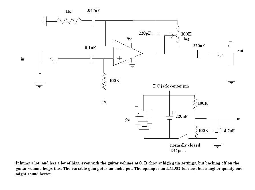
I think i'll retry this with a socket, and get one of those higher quality opamps. If in the meantime anybody sees an error in my schem that can be fixed, please notify me. I have switched the leads of the power supply so that it matches the schematic exactly. The current state of operation is:
with battery power, I get a lo-fi fuzz effect with almost no sustain; it just craps out when the volume gets low. When plugging in the power supply(and therefore cutting off the battery power) i just get a whooshing sound, completely devoid of my guitar signal. I'm not chained up to any other pedals, so thats not the problem.
-
That's your latest configuration?
I thought you said before that your gain pot was where the 1K resistor is and that what you're showing as a 100K log is actually a 100k resistor. I think that is where it should be, not where it is shown in that drawing. The way it is now, it will try to go to gain <1, which will make it unstable. I also think it should be a linear pot when you're working gain. Making that a linear pot and moving it will help with the jumpiness.
no the gain is "r1/r2 + 1" so the gain is never less than 1.
well before i worry about the pot taper i have to figure out why it sounds like a lo-fi fuzz box.
-
But where would it even be useful?
Obviously where ever you're using your pedals you're using an amp so mains power is present to plug you adapter into.
The only situations I can think of are whilst busking with a battery powered amp or when your power circuit is so close to capacity plugging in your adapter would trip the breaker
well as a college student i would like to be able to listen thru headphones so as to not piss off my rommate, and then if i want to move away from my pedalboard i would like to attach the unit to my guitar strap (with the unit now on battery power) and make the amp more portable.
-
grrrrr
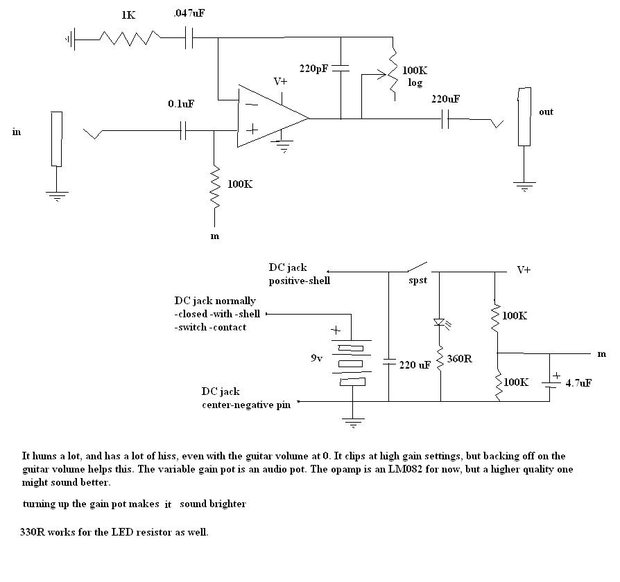
i got it set up, but i get no signal through the headphones. just pure hum. i'm gonna check all my connections, but here's my schematic as of now. does anybody see where i went wrong? I added a DC jack for a 9v input. there are 2 connectors that are "normally closed", and when the DC plug is in, one of them is the shell and the other is not connected. the node labeled "dc jack center pin" is not involved in the switching.
the reason i added this is so that when my 9v adapter is plugged into it, the adapter powers it. then when it is removed, it goes to battery power. right now i get no signal on either power source. any help? ive done plenty of continuity checks
i wonder, was i supposed to use a heatsink when soldering my chip? cause i didnt. could i have burned out the chip? and how do i check for that?
ps. when i touch the pot shaft (or even put my finger near it) the hum gets louder. im using a plastic enclosure(all radio shack has, and my altoids tin won't fit a 1/4 in jack).
EDIT: ok, i didnt change anything, and now with the battery supply it sounds like an extremely low-fi fuzz box. and the pot taper has problems, which, btw, it has never done while in the gain-control configuration. there is no sound in the power supply operation (but i'm in the process of correcting that) can anyone spot the reason for my fuzz ?
-
well idk how to really measure my guitar's max voltage swing, i think i'm just gonna have to get by with the variable gain config.
You'd need a multimter with a sample and hold peak detector. Pickup manufacturer's sometimes post this information, but it's a big window at best.
my setup now (with the 100k gain rheostat) is really really dark on the low gain settings, then theres that fast jump up to LOUD, and then it starts to clip. I think i'm gonna have to set this thing right on that edge, and find the sweet spot, and if it's clipping just back off on my guitar's volume. It's too much work, but oh wellThat's unfortunate. I'd really hoped to see this worked out. Have you tried playing with capacitor values?
what opamps are better than the TL082 i'm using? i was told that was an "audio" opamp. which are the better ones?As we said in the beginning, the TL082 is better than an LM741. The TL072 is a lower noise version of the TL082. Still, all of these are general purpose "penny" chips because they are outdated by newer technology and you can buy them on the penny.
Here's an interesting page, though it's 5 years old. Even then, the TL082 was outdated. http://tangentsoft.net/audio/opamps.html
Take a look at this and order yourself some free samples... http://www.linear.com/pc/productDetail.jsp...009,C1026,P1293
This one looks just right for you IMO... it should be more output, less noise, and, you can get free samples... http://focus.ti.com/docs/prod/folders/print/opa627.html
yes, i've tried playing with capacitor values. i either get much noise or a dark sound. i opted for the small value cap ("much noise") and i can keep tabs on the noise by rolling down the gain knob.
thanks for all those resources. i would get one of those better chips, if i hadn't just finished soldering my PCB and prepping my enclosure. this thing should be finished by this time tomorrow (hope it works!)
-
This would be easy enough to do you just need to add the charger circuit (a 9v battery charger is not simply a 9vdc supply) put in a 9v rechargeable battery and rewire the jack to charge the battery.
IMO its not a large enough improvement over conventional rechargeable use to warrant doing. Of course its the perfect solution for those too lazy to take the battery out and put it in a charger
Just get a proper power supply and be done with batteries altogether, saves energy and money in the long run and (for the greenies out there) does away with the environmental implications of batteries.
i must just be one of those lazy people. actually i have more of a problem with HAVING a charger than USING it. if I could do with no charger, just a 9v supply, that would be awesome. one less thing to worry about losing.
-
Does anybody know of a 9v power supply that basically acts in this way: you put it in your guitar or pedal, and it acts as a battery supplying 9vDC. When you plug in a 9v adapter, the adapter powers the electronics AND recharges the battery. Then if you need to unplug the adapter the battery is still inside.
Has anybody heard of this? I assume if it existed it would be implemented in many, many stompboxes and guitars.
-
well idk how to really measure my guitar's max voltage swing, i think i'm just gonna have to get by with the variable gain config.
my setup now (with the 100k gain rheostat) is really really dark on the low gain settings, then theres that fast jump up to LOUD, and then it starts to clip. I think i'm gonna have to set this thing right on that edge, and find the sweet spot, and if it's clipping just back off on my guitar's volume. It's too much work, but oh well
what opamps are better than the TL082 i'm using? i was told that was an "audio" opamp. which are the better ones?
-
oh and btw i get some really nasty clipping when the gain is up. turning down my guitar volume helps this a bit, but i'd rather not have to.
-
Is your 100K log in that drawing what we've been discussing as your "volume"?
oh no, currently i've got a 100K fixed resistor there. My volume is a standard passive volume after the capacitor. By the way, when I had my variable resistor in the gain stage, the taper was perfect.
I'm at a loss, unfortunately. If no one else can help you, you may as well go back to just a variable gain if that worked perfectly.
well the only problem is, idk how to put a treble bleed mod on the gain control.
-
Is your 100K log in that drawing what we've been discussing as your "volume"?
oh no, currently i've got a 100K fixed resistor there. My volume is a standard passive volume after the capacitor. By the way, when I had my variable resistor in the gain stage, the taper was perfect.
-
I've always been intimidated by dual supplies, but now that I've seen how much easier it is to use op amps with dual supplies, I'm not going back, at least for audio applications. The space savings alone with regard to the PCB is enough. Without the need to create a VCC/2 and all the extra capacitors, the tradeoff is well worth it.
well, i would like to be able to power this with a 9v wall adapter. How would this work with dual supplies? Like this?:
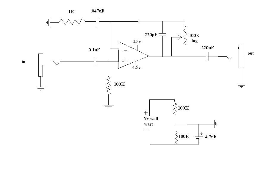
but what if it was daisy chained with other single supply units? (i have a power distributer) Wouldnt that screw it up?
-
my 10k pot is linear, so forget that.
what i did is put a 47k resistor between the wiper of the 100k pot and the headphone jack tip. This made my pot a bit smoother, although not completely smooth, however there is volume loss. I dont think it's a good idea to put a resitor there,but what I found out is this: headphone impedance WAS the issue. putting the resistor was increasing the impedance, therefore having less effect on pot taper.
i have not been able to translate this into a solution, though. i don't wanna have to use special ultra-high impedance phones for my amp. i wanna be able to use any phones.
-
It looks like 240-300 (55.1 jump) and 300-360 (11.5 jump) are defective and should be reversed and even then are not so smoothly logarithmic, so that might exhibit a jump in perceived volume, not to mention that you should have 0 at 0, but that alone would not give you the jump behavior. Do you have a linear pot or another log pot you can test perceived volume with?
Would you say you are getting some volume the moment you turn a small amount from 0 degrees? Please estimate the degree amount where you first notice sound and the degree amount that the jump occurs.
ok i went buy another radio shack pot, 100k audio, and i get the same exact problem. I've tried wiring it forwards, backwards, etc. no luck. I'm using the wiper terminal to connect to the headphone jack tip.
I think the problem is really that the impedance is too small on the headphones. they are altering my pot taper. how can this be fixed?
the jump occurs about where the chart indicates: 240-300 deg.
i'll try a smaller value pot; 10k.
also note that the chart i gave is very very vauge. i did not have a protractor on hand.
-
I think your pot is suspect.
i measured resistance of my pot from i pin to wiper at degrees of rotation in 60 degree increments (it's actually a bit less than 60. maybe 57). Here is the chart:
deg. Kohms
0 1.5
60 1.5
120 4.45
180 10.5
240 24.9
300 84
360 95.5
looks pretty standard logarithmic to me, considering it is a rough test. (except that 240-300 stepup?)
-
I haven't read the entire thread, but I think the failure is largely to do with this being basically a preamp kind of circuit where you need the power of a power amp circuit to drive a speaker or headphones generally. The ubiquitous LM386 meets the bill for this kind of thing with battery power as on the various "ruby" like circuits based on it...another approach is to use power transistors fed by the opamp circuit to push the power through to move speakers sufficiently.
I am not sure of this analogy, but you could look at the speaker or headphones like a big (generally 8 ohm) resistor...you may be getting the gain but not the "power" to move this obstacle at the end of the circuitry. What you are getting is a lot of voltage gain from such circuits but not current gain...so perhaps an analogy is you are getting a lot more water but not the flow rate to move the speakers when it hits that resistance...maybe an analogy would be a hose running up hill, you can have as much water at the bottom as you like, but it takes some pressure to get it to run up hill!
However, such circuits are useful if not necessary on the front end of power amps like the LM386...you need them to prevent loading down the guitars signal as generally power amps have a very low input impedance (like resistance)...such opamp or transistor circuits before the power amp stage help to condition the incoming signal from the guitar to "match" the impedance and not offer a tone robbing obstacle to the guitar itself.
Hope that hasn't confused things even further...
pete
so what you're saying is i don't have enough power? All the headphone amp schems online said that low output impedance is the way to go. But now that I think about it, guitar amps and cabinets need to be matched to get the best power transfer. Do I need to match the impedance to my headphones? how do I do that? is there a way without transistors (i am a beginner and i'd rather not venture there just yet)?
and btw, how does this have anything to do with the taper of my pot? as i understand it, my headphones are altering the taper. Will increasing the amp output impedance change this effect?
-
Other op amp models with better specs.
um, that doesnt really, i still don't think i understand. You want me to get a better opamp? and that's gonna make my volume control even? how would it do that? lower impedance?
?
-
OK, for some reason I thought you had your gain setup the other way around.
Maybe like you said and someone mentioned back on page 1'ish, it is the addition of the headphones that is doing it. Can you try hooking the output up to a different system, like a guitar amp or a set of PC speakers to see if the result is the same?
i'll try it, but, well even if that is the problem, it doesnt really seem fixable. i mean, how would i be able to have a headphone amp... without using headphones?

Sustain In Guitars?!
in Electronics Chat
Posted
dude you hit the jackpot by coming to this site. there is a thread pinned to the top called "sustainer thread" or something. it has like 300 pages of how to make your own sustainer.