


AndrewCE
-
Posts
121 -
Joined
-
Last visited
Content Type
Profiles
News and Information
Tutorials
Product Reviews
Supplier Listings
Articles
Guitar Of The Month
Links and Resources
Forums
Gallery
Downloads
Posts posted by AndrewCE
-
-
Well, what's the performance like now anyway?
I'm assuming the sound you got is entirely clean or does it have some dirt to it as well?
well, it's entirely clean as far as i can tell. I'm using a tech 21 blonde pedal as an amp simulator (its not great, but it works).
wow, you took off work to work on an led project?
 sorry i just find the irony funny for some reason
now, i tried to add a post-gain volume control, and keep my gain stage at a fixed gain, but here's what happens: even though i have a log pot, as i adjust it, the volume is at zero, then at some point in the sweep it jumps up to max volume. I've wired the pot up several different ways, and I can't get this problem to go away. I assume it has something to do with the opamp's low output impedance and the fact that i'm using a 100K pot. But i tried it with a 10K trim pot, and i have the same problem. any solutions?
-
I admit I felt some negativity in that last post when i saw the filenames,
well sorry if you misunderstood, it was only a joke.
i'm actually hoping to move towards a wall wart supply, so ill keep the cap
yes, i know it's "good practice", i was only saying that this specific application is an exception; i understand most other, bigger projects would be better organized if done the way you were suggesting
less than ideal because "M" is not really static as a 0V Gnd is. "M" is an ever-movinghm, i'm not so sure about that. maybe if youve got a wall supply, where "ground" is actually connected to the ground (is it, actually, in a wall wart???), then the 0v would be more constant than the 4.5v. But with a battery, if the voltage all of a sudden jumps from 9v to 8v, i think the best way to describe what happens would be: the "9v" node jumps down by .5v, the "ground" node jumps up by .5v, and the 4.5v node stays where it is. This is because the "ground" is not actually anchored to anything big, like the actual ground. And it is best understood how the 9v battery reacts by viewing it as 2 separate 4.5v batteries, as is shown in one of my "sarcasm" drawings. This seems like more of a philosophical discussion of relativity than an application discussion, though.
um, what is the "shift typing sequence"?
-
yeah i named em on the off chance that you would be able to see them, lol
Thanks for the drawing; ive noticed two things:
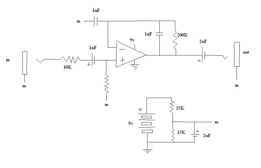
1. Your r6 does not exist on my schematic. An early version of my schematic had a 10K resistor in that spot, but nobody could tell me what it did, and removing it didnt change the sound of my amp, so I omitted it. could you tell me what R6(in your schematic) does?
2. You've omitted the 220uF cap from 9v to ground that you were suggesting. I'm guessing this was just a slip-up?
4.5VDC can not make it past the output cap. That defies the nature of the capacitor.right, there is no voltage bias after the output cap. UNTIL you plug in a pair of headphones. Then youve got 37 ohms (DC resistance of my headphones) connecting the sleeve and tip, biasing the output side of the output cap so that the signal swings above and below whatever the sleeve is. Thus, it does not matter what the charge of the sleeve is relative to some arbitrary point such as the negative terminal of the battery. It matters what the charge of the sleeve is relative to the output tip connector. And this voltage will be 0V, regardless of where the sleeve is in relation to that arbitrary point.
idk how the sleeve and tip measured 4.5v with the sleeve attatched to ground, but it did. and i repeated the experiment, and the results were the same. (as far as this little experiment, i'm puzzled)
yes, and btw, i hope you dont take my stance as me trying to be difficult, or trying to disrespect you; i'm just trying to learn what i can about circuitry, and at this point i do firmly believe that the constant voltage between sleeve and the battery's negative terminal has no effect on the DC voltage b/t tip and sleeve
-
-
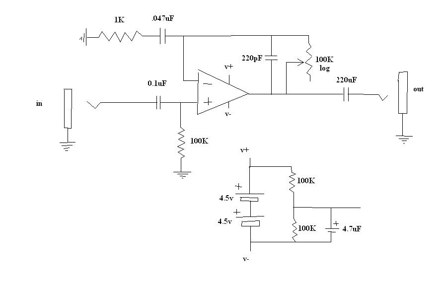
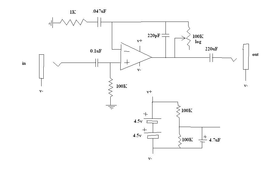
ok now, i've drawn up these two new schematics. The only difference between the two is what the sleeves are connected to. Tell me which one of these 2 will work better. Anyone else care to chime in on this?
-
If you don't believe me, get a volt meter. You will see 4.5 V on your output. This is not good. I am only trying to help, but unfortunately,don't know how else to convince you. Good luck.
I connected the voltmeter so that 1 lead was on the sleeve of the output jack and the other lead was on the tip connector of the output jack. The way my schematic is now, with sleeve connected to "m", it read about -50mV. When the sleeve was connected to ground, it read 4.5V! Then I even connected BOTH sleeves to ground, and it still read 4.5V. If you don't believe me you can breadboard one yourself.
-
On the output side, before the signal passes the 220uF cap, it has the DC offset of 4.5V on it. The purpose of the output capacitor is to remove that 4.5V and bring the signal back down to a true AC, centered around 0V.
Centered around 0v? are you sure about this? When I passed the signal through the input coupling cap, all the DC was removed. There was only AC. And I was required to put the 100K resistor to "m" to tell the signal what constant voltage to swing above and below. It doesn't just know what DC voltage to use. So why would the signal after the output coupling cap "know" what DC voltage to use? It doesnt. You assume that the AC signal would choose ground by default, but it doesnt. It'll use whatever you give it. Here I gave it "m" via the sleeve, so it swings above and below "m", which is perfect, because the sleeve is at voltage "m". It works exactly the same as if i connected the sleeve to ground. If you don't believe me, look at that underlined sentence and try substituting "ground" everywhere you see "m". It holds exactly the same truth value!
remember, voltages are relative. They are not values of charges but instead they are differences between charges. If an AC signal is riding on 4.5v, the 4.5vDC is irrelevant as long as the place to which the AC is flowing is also at 4.5v. Note that the entire post-output-cap circuitry is not even connected to ground(except by the 100K power supply resistors which can be ignored). So the current isn't flowing from 4.5v to 0v, it is in fact flowing from 4.5v to 4.5 v. So there is 0 DC current.
-
The pot in the feedback loop is a gain control, not a volume control. If you put a pot on the output, that is a volume control. There is a difference, in that gain is a multiplier of the original signal and can never be less than one, unless the circuit is setup as an attenuation circuit, but yours is not. Volume is what allows a reduction of the total (post gain), all the way down to zero. If you can get zero, it probably is not a true zero, but if it functions to your liking, it is not a waste either.
The cap config for "M" that you mention, I have not seen that one, but do not think it makes much of a difference, other than series capacitors half the capacitance, so it doesn't sound like a good thing, since higher capacitance is better there (lower corner frequency for the low pass filter) but I could be wrong there on why they did what you saw.
The active "M" allows you to bring "M" to other parts of the circuit (like another signal entirely) without worrying about the crosstalk so much,for example if you were building a mixer out of many op amps. Right now, if you connect "M" to other signals, they may bleed into one another, but with the active "M", there's more push-to-"M" power for lack of a better description.
Yes, jumpering the tip and the ring will give mono in both sides, but will reduce the output as well. To get around this, you can use 1/2 of the TL082 as a right and 1/2 as a left, then you won't lose volume and you'll have 2X the output you currently have.
Very importantly, in looking at your latest schematic, I do not believe you should have the sleeve of the input or output connectors going to "M". I think those should go directly to system Gnd, 0V... not the 4.5V "M". That is VERY likely to be the cause of the rest of your hiss. What is happening is you are adding a 4.5V bias to the input before you are even into your circuit, then removing it with the 0.1uF cap on the input (undoing what you've done by connecting "M" in the firstplace). Then, at the output, the 220uF cap removes DC bias (the "M"), but after that you're adding it back again. That is going to add noise and reduce the life of your speakers... they don't want a DC bias. They want to be in their natural resting position... having "M" connected to the output is liking putting an offset to the speaker cone and reduces headroom.
i'm ok with just having a gain control; I dont need zero output, and if I do, I'll just unplug the unit.
as far as the capacitors, i've put a 220uF across the 9v potential, and i didnt hear the noise change at all. but when I unplugged the battery, the cap took a second to decharge, and the output made a quick flanging-like sound. i dont know if the slowly changing supply voltage is HURTing the circuit or not, but I'd rather not chance it if i dont have to. especially since the cap doesnt make any audible difference.
i dont think i'll need to use an active "m" nor will i have to use the other half of the chip; my output is good, i'm only dealing with one signal,
as far as where the sleeves are connected, i'll play around with it but i really think it should be "m". In an actual ground circuit, you wouldnt connect it to the -9v, you would connect it to the spot halfway b/t the 2 supply rails.
[Actually, i dont think it should make any difference.] as the input sways between +-3mV (or however big the guitar signal is) that is basically telling the circuit to go that far above and below "m". the 2 caps isolate DC from the circuit, and the headphone recieve the difference between output and "m". Since the input swings above and below "m", so will the output, and so the voltage across the headphones will always be +-10mV (or whatever the amplified guitar signal is).
oh and one last thing, that treble bleed mod. it seems like the 220uF feedback cap is already acting as a treble bleed mod for the 100K pot. i'm sure the value is off, but what i'm saying is, to add a treble bleed mod would be pointless, because it would effectively be the same as increasing the value of the feedback cap. wouldnt it? correct me if i'm wrong... i would like to have a more even eq across all volumes if possible
-
man, i thought this thing sounded decent before, but WOWWWWW! I just replaced the 741 with a TL082. godddangggg it sounds so crisp.
there is still hissing there, but it is reduced.
i think all i need to do is that treble bleed mod, then solder up (unless you have another suggestion based on my last post)
-
OK, I just noticed a rather large design issue. I did not realize before you have a volume on the input! This is not the best way to go for signal-to-noise-ratio reasons. This is part of your noise problem, in my opinion. I would lose that altogether, so you are allowing the full guitar signal in and adjusting gain (and output volume) as necessary. Put a 100K pot in where you have the 100K resistor in the feedback loop. Where you want a volume control is on the output (after the output capacitor).
Yes, your tone will be more trebly when volume is up and it will lose highs as you go down. This will happen with any value standard pot. Not that it is a good thing, but is normal. This is just like what happens with a standard guitar volume. You can do a treble bleed mode, like show on this page... read whole page: http://www.projectguitar.com/tut/potm.htm
...or, if you want it to be less trebly, then adjust the value of the cap in parallel with the 100K resistor in the feedback loop. A larger cap should yield less treble, but make small adjustments there!
Yes, the TL082 lacks those pins because it is internally compensated and does not need offset nulling.
No, DO NOT remove the cap between "M" and virtual Gnd. It is serving the same function as the 9V bypass cap, but in a different spot. Removing it would reduce performance and increase noise. As far as you rpoposition of:
9v -> cap -> virtual ground -> cap -> ground setup. Would that do the same thing?...can you draw that? I'm not quite following you there. However, since the TL082 is a dual op amp, what some designs have is one half of the TL082 doing a different version of an active "M" that can serve as a "virtual Gnd" for many other op amps, whereas your passive "M" can not do so without affecting the rest of the circuit. Then, they use the other half for the gain section.
yes, someone had already notified me of the pot issue. I put a 100K log pot in the feedback loop. are you saying i should put a second volume control after the output cap???
you know the 2 100K resistors between 9v and ground (creating the virtual ground)? well one of those resistors already has a cap in parallel with it. I have seen some power supplies where both resistors have a cap in parallel with them. So there is one cap b/t 9v and m, and another cap b/t m and ground. would this do the same thing as adding the cap from 9v to ground?
I looked up what you mean by a "version of an active m". What advantage would that give me over a passive "m"?
question: i have a 1/8" stereo out jack. if i just solder a jumper connecting the left and right channels, will that make it mono (and give me sound in both ears)?
edit: this is what it currently looks like:
-
Are you getting enough overall volume? The standard opamps such as 741 have an output resistance of 75 Ohms. Headphones, such as used with mp3 players have quite low resistance, mine measure 16 Ohms, or 8 ohms if both sides are being driven. So the chip cant drive the phones to more than about 10% of the available voltage swing, which is about a 20db loss. A couple of transistors in a push/pull configuration to drive the output might help.
well i'd really like to do this with no more active elements than a single op amp. especially since this is my first self-design project. Also, i was led to believe that opamps had really low output impedances. i guess 75 ohms is pretty low, are you saying it's not low enough? how else can i fix that problem without transistors?
-
First off, congratulations on getting where you are. You should be proud. This stuff frustrated me for a LONG time.
Paul is correct. The LM741 is a "general purpose" op amp, not specifically intended for audio. You are probably always going to have some noise unless you modify your choice of chip. However, I do think we can do 2 more things to drastically reduce the noise you have now. I have not mentioned them previously because we were already throwing a ton of info at you and may have been overwhelming and I considered it much more important that you actually get sound and gain first.
The best news of all here is that if the following 2 things don't do the trick, then most of the other 8-pin DIP package op amps share the same pin configuration, sort of a standard, so switching from the LM741 is a simple pop-out-old, pop-in-new.
1.Condition the battery power going into pin 7 of the LM741. To do this, add a 100uF (or larger) cap from pin 7 (V+) to Gnd. This forms yet another low pass filter, sending a great deal of the AC spikes/dips from the battery to Gnd and allowing just the bulk of DC to get to the op amp's power input. Not doing this makes a pretty big difference in my experience. The connection to pin 7 should be as close to the body of the component as possible, NOT at the end of a long lead, to avoid any other induced currents long the way to the pin.
2. Balance the inputs. The LM741 (and all differential op amps) are subject to minute variations in the manufacturing process that makes them "less then idea". This means they have some error in the inputs, referred to as input offset current. When you apply gain to a signal, the error is amplified along with the signal. To get around this, the manufacturer provides pins for measuring and "nulling" the offset, sort of like a calibration procedure which restores the op amp to a more perfect balance, thus reducing any imbalance, reducing error, and reducing noise on circuits with gain. Look at this page and go about 3/4 down, check out Fig. 11 and the procedure there. Unfortunately, you need a multimeter to do this.
http://www.uoguelph.ca/~antoon/gadgets/741/741.html
I think you are right about the one other resistor. I could not find any documentation to support this, buyt I seem to remember that there should be a resistor somewhere in the circuit that is the parallel sum of your R1/R2 gain resistors. I have never bothered with these as I never had a static gain setting, I always use a potentiometer for variable gain, so that resistor value would need to change every time I moved the pot... not practical.
If you've been going to Radio Shack for your components... try the TL082 op amp. It is better quality and provides 2 op amps in one 8-pin chip, so you could do stereo and get the benefits of pre-balanced inputs and JFET inputs, which are better than the bipolar transistors the LM741 utilizes.
thanks, i'll do those mods. i'm also gonna remove the 10k pot, and to adjust volume i'll get a 100k audio pot for the feedback. at this time my tone gets more trebly as i turn up to volume; i dont think it should with the new gain-changing setup. (or should it?) Also, since i'm changing my gain, will i need to change some other resistor? (you mentioned something about the r1/r2 parallel value?)
i got a TL082. one question: it doesnt have any offset null pins; do i need to adjust the offset null? the package say "internally compensated". does this mean that i dont need to?
also, if i add the cap between 9v and ground, can i remove the cap b/t "m" and virtual ground? And I've seen schematics that just have a 9v -> cap -> virtual ground -> cap -> ground setup. Would that do the same thing?
p.s. i dont think i'll be doing the stereo thing; i really only have one input signal to work with: my guitar signal
-
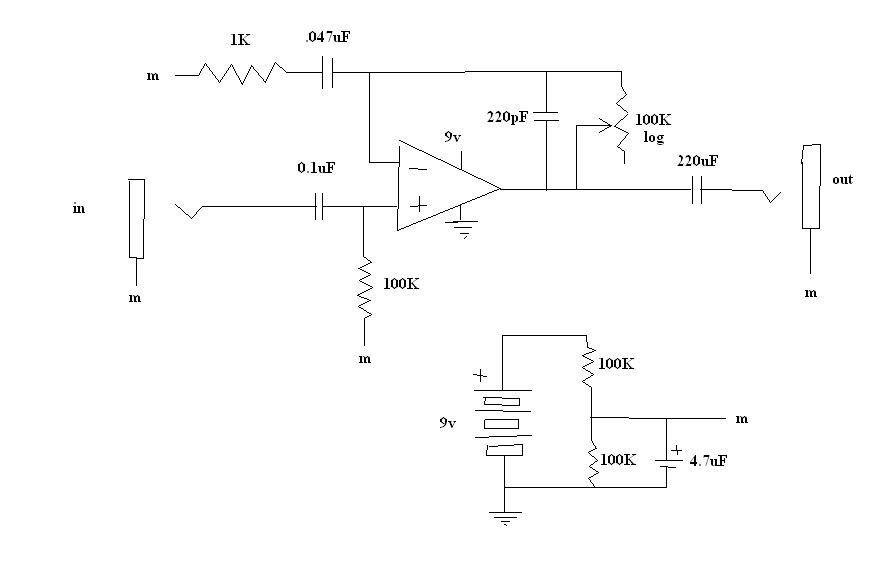
Thanks guys, here's the current schem:
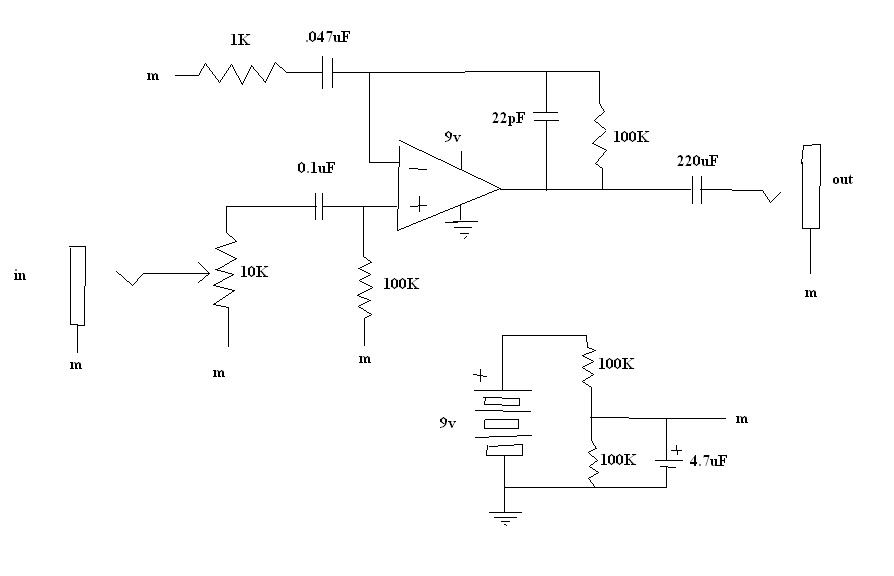
I'm about ready to call this thing "final". The gain is good, the only problem is, it's noisy. There's a constant hissing. The only way I've figured to make it go away is to increase the value of the feedback cap, but then the tone gets all dull. Unless someone has a few quick tips on how to reduce noise, I'll move this thing from breadboard to PCB.
btw, I believe the MXR Dist+ equivalent of my 100K to "m" is MXR's extra 1M that goes into the network of 1M resistors. This answers both the question of where to connect the other end of the 100K and why my design doesnt include that extra resistor (it does!).
and i'm assuming that a ceramic cap reading "10" means 10pF. correct me if i'm wrong.
-
One quick question: i got some assorted orange ceramics, and they only have numbers on them. What is the implied unit?
-
The cap in parallel with 200K forms a low pass filter, rolling off the highs... the right value attenuates frequencies above the audible range (20kHz).
I am holding that that other cap does need to be connected to ground. Study the MXR schematic a bit more. Notice after that cap (a .047uF), they have some more resistance (a 4.7k followed by a 1M potentiometer). That is KEY! ...not the exact values, but the premise. You're blocking DC going to ground, and allowing AC to go to ground. This is what tells the op amp that it needs to boost AC and not boost DC. Op amps amplify difference between the inputs.
Also notice that in the MXR schematic, their "M", formed in the top half of the drawing, uses 1M resistors to form the 4.5V, then yet another 1M resistor in seried before connecting it to the + op amp input. You might try that. In any case, using higher values there than your 15K's will save battery life AND reduce noise because higher values will allow less curent through and bring the low pass filter's F to a lower number, providing a cleaner "M" reference voltage.
At this point, I am convinced your cap values are your biggest problem.
I do not think you need to worry about impedance matching. Op amp inputs are high impedance, so they won't mess with your guitar in a backward manner. The outputs are low impedance, so they should be able to match high and low impedance on the next stage without a problem.
What might be an issue is that the op amp's output current is not all that high, so it might have trouble driving headphones, I'm not sure as I've not tried it. I used the LM741 to drive as a preamp, not an actual amp, and it works excellent. You might want to try hooking up the output to alligator clips and clip them onto another guitar cable going into your normal amp in order to test easier, at least for sound quality and to see if you are getting any working gain.
Get some potentiometers when you go to RS. Yes, their prices are about 100X higher than buying online, but nothing beats them for the sheer convenience of it... mine is a 20 minute drive, which equals no wait for delivery and no minimum orders like you may find online.
Anyway, I think you're on the right track. This can be a long and frustrating road your first time, but once it clicks, imagination is the only limit to the kinds of projects you can embark on.
so, let me get this straight... the feedback capacitor is a lowpass filter, and the cap to ground is a highpass filter? I think i'm finally getting that. Is that correct?
[me thinking out loud] if it is, then the whole thing is a bandpass filter, and decreasing the size of each capacitor shifts the edge of the "band" up in frequency... increasing the cap size shifts it down... right?
i already changed over to 100K resistors for the virtual ground. I was hoping on the off chance that my lack in gain was due to that network draining my battery. No luck. and in retrospect, it sounds pretty stupid. I'll keep them there anyways, they didnt change the sound.
yes a pack of assorted low value caps are first on my list for tomorrow.
I did see that extra 1M and i was wondering about it. I'll try it tomorrow, but until then, um, could you explain what it does?
btw, thanks for all this help youre giving me. and sorry if i ask too many questions [my mind is a sponge]
-
I think you need to do a few things.
1) Where you have your feedback loop connecting to "M", I believe that needs to go to ground, meaning the same place the battery negative goes. Also, there really needs to be a resistor where you removed that one. That, along with your 200K resistor are what sets the gain. In your current configuration, there is no gain loop, at least in the conventional sense. I think you are getting "open loop" gain, or something close to it, which is the op amp going wide open. What most setups have instead of an actual resistor (where you removed yours) is a potentiometer. Gain in your configuration is G = R1/R2 + 1, where R1 is your 200K and R2 is the one you removed. A 200K pot in the spot you removed that resistor from yesterday would let you vary gain from 2X to whatever the open loop gain of the op amp data sheet says it is, within the bounds of the power supply.
2) If you can, try changing the cap values. They play a really big role in what gets amplified and what gets attenuated. I think your values are too large, with the exception of your output cap. Since the cutoff frequency is F = 1/(2*pi*R*C), you can see that F becomes smaller as R or C becomes larger, so what this means is that for a low pass filter (formed in the feedback loop), the bigger the cap, the lower the cutoff frequency, and the more that highs will suffer.
a) Try a 0.1 uF in place of your 1 uF input cap.
Try a 0.01 uF in place of the cap that's in parallel with your 200K resistor.c) Try a 0.047 uF in place of your cap that goes directly to "M", but again, that should not go to "M", but rather to ground, ground being same as batery negative.
Lastly, in answer to your question, none of these caps ned to be electrolytics. In fact, you will have a hard time finding electrolytics in the values you most need. You need smaller values, probably a good idea to get a cheapo $5 kit from Radio Shack . You need values from .001 uF up to 1uF to experiment.
Look at this circuit, I believe I got this from DIY stompboxes.com. It has the same general setup that you need to accomplish with regard to ground, "M", and the gain feedback loop. I built this and it works kicka$$

yeah i actually found that exact same schematic, but I didnt have the right value caps on hand. I'm hittin up radio shack tomorrow (but damn, radio shack is expensive).
you know, i still don't get what the cap in parallel with the 200K DOES. it seems to decrease the gain as frequency increases. why is that important?
and i connected that other cap to ground instead of "m". it sounds exactly the same. I think it's actually supposed to go to m, because, if you think about it, connecting it to ground would be the same as: if there were no "virtual ground" and the cap was connected to -15v (and that wouldnt make much sense).
i've done all of your modifications except for 2B, which i'll do as soon as i get the right cap. and it still sounds exactly the same. I wonder if i'll need more than 200K ohms.
p.s. what do i need to know about impedance matching? some sources say the impedance needs to match the headphones, and some say you want the lowest possible output impedance. ???
-
all polarized caps are electrolytic. all resistors are metal film. all nonpolarized caps are metalized film. "m" is the virtual ground. My headphones measure 37 ohms DC.
the signal is clear, but not loud enough. i've tried short circuiting the inverting input to "m", and that forces it into clipping (square wave buzziness). I've tried short circuiting the inverting input to ground, and I get no audible signal. I've tried putting a 1K resistor from inverting to ground and I get no audible signal. I've tried putting the 1K resistor from inverting to "m" and the signal is audible, but just as weak as it is when there's no 1K resistor there(how the circuit is in the schematic).
any help on how to up the gain cleanly?
-
ok, i added a 1uF cap in parallel with my 200K feedback resistor, and another 1uF cap from inverting to ground. This gives me a fairly clean sound. for some reason i removed the resistor from inverting to ground(theoretically that should take away my gain of 200, but after doing it i am still able to hear the sound *???*), and that magically got rid of the buzziness.
My only problem is that I don't have enough volume. I can hear the sound, but I want it to be louder.
I'll draw up a schematic to clarify my problem. (But i'm getting excited, it's almost up and running!!!)
-
15K resistors will eat battery quicker,but should work.
Everything that was connected to GND should still be connected to ground, with the exception that MAYBE the 1K resistor could go to "M", but I don't think so. Try it going to GND first. Make sure the op amp negative power input goes to GND, not to "M".
The 10K and 100K resistors... not sure about the 10K, but the 100K and the 1uF cap make a high-pass filter. The 10K may be noise-minimizing or impedence-related. Both of those resistors should be able to be removed without killing function.
Lastly, I THINK that another thing they are not telling you is that for your gain to work,you'll need another cap. In your drawing, insert a cap directly to the right of the 1K resistor. I believe this is th eonly way to get gain working in the config you have.
Do a search for "MXR Distortion Plus Schematic" and check out how the opamp is set up. It is as bit more complex, but shows how a good gain is set up.
What op amp are you using?
update: i actually got it to "barely" work now without any changes. The key was to get a loop pedal to feed the circuit, instead of trying to strum it while probing (duhhh). Also, it's nice to now have working 9v and output jacks for a solid connection.
THERE IS a problem, though. The sound is very buzzy. It almost sounds like a square wave. I was under the impression that this amp would be super clean; almost disgustingly clean. Any ideas on how to clean it up? I think I'm gonna try that feedback capacitor thing donovan was talking about.
a single 741 opamp
p.s. Do all these caps need to be electrolytic? What is the best type (metal film, carbon, electrolytic, nonpolarized electrolytic)? And is there a "best type" of resistor?
-
and btw, this is prob a dumb question, but what is the purpose of the 10K and 100K resistors at the input part of the circuit?
-
well, i do know that if I, or another person, is standing next to the guitar or holding it, and the person is not grounded via the strings, then that person is acting as a satellite dish for hum. the hum bounces off of him and gets all up in the pickups. a truss rod could possibly do that. but i'm not sure to what extent...
-
ok, i just added the power supply donovan drew up in the gray box (except with 15K resistors and a 2.2uF cap), and now all the things in the original circuit that WERE connected to ground are now connected to "m" (my name for the vcc/2). I even connected the "ground" terminals of the input and output jacks to "m". Was i supposed to do this?
p.s. I also am using a 200K feedback resistor (gain of 200) and a 2.2uF output capacitor instead of the output resistor.
and it still gives me no sound
any thoughts?btw, great resource, donovan! thanks. i read almost the whole thing!
-
One problem I can see is that your feedback resistor is really small, so it will have very little gain. I would try something like a 220K instead and see what that gets you.
And the other thing that you have to take into consideration is the impedance of the headphones that you plan on using.
These pages might help point you in the right direction with designing a headphone amplifier circuit:
believe it or not, that 2nd link is the exact page that i was referencing when i drew up the schematic. It only uses a gain of 10, so I did too (with the 10K feedback resistor). what changes would I have to make for my headphone impedance? (and how do i measure headphone impedance?) I thought that an opamp has theoretically an infinitely low output impedance. That should be a good thing, to drive headphones, right?
-
thanks anderekel
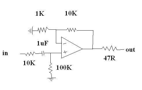
here it is. I've tried it with and without the output resistor. all resistors are metal film. the cap is electrolytic. I'v done continuity checks. My power supply is a single 9v batter with one side connected to each opamp power supply.
My test is to hook up my strat, strum the strings, and listen through headphones to the output. I hear nothing.
I'm so upset because from what I've read this is literally the simplest project out there, and I can't get it to work.
any help would be greatly appreciated.
 sorry i just find the irony funny for some reason
Failed Headphone Amp
in Electronics Chat
Posted
I have it hooked up literally exactly the way you do, with the exception of C6 and R6. And my R4 isn't a pot. It's a fixed 100K. And my volume pot is a 100K log pot, but it's still doing the jump-up thing.
????????