


AndrewCE
-
Posts
121 -
Joined
-
Last visited
Content Type
Profiles
News and Information
Tutorials
Product Reviews
Supplier Listings
Articles
Guitar Of The Month
Links and Resources
Forums
Gallery
Downloads
Posts posted by AndrewCE
-
-
I'd try around 70-80Hz, you could get that just by adding another .001uF in parallel. You may even need to go lower and use a third .001uF cap for about 50Hz, but I doubt it.
edit: btw, .001uF and 1Mohm is 159Hz. And how is 4th string 2nd fret an E? Isn't that an F? Or do you mean on guitar? In that case it'd be 330Hz at that fret, 165Hz at the 6th string open E. Lowest note on a bass is 82.5Hz, but the Q of a filter like this is probably pretty big so I think 80Hz or possibly even lower would work.
edit 2: Wait, by the diagram it looks like you have it wired as a volume knob with a treble pass, not a tone knob.
Volume:

It should be wired like this, in parallel with the output, not in series:

he's trying to cut bass, not treble
-
solo frequencies:

to the left of the circuit looks very interesting, but i'm lost, looking at everything east of those diodes (that could be attributed to a sloppy schematic, or the fact that I don't know what the 4 plugs are on an oscilloscope). I guess my first question is, why so many capacitors? They are all in parallel, so can't you just figure the equivalent capacitance and use one big cap?
-
Well if you have the caps their in the rectifier circuit, it cuts the power, to the RMS voltage, and say you have a 5Vp at the diode, you would now be producing a 3.535 Vrms DC voltage after the capacitors, so in theory, I'm not disobeying the laws of Physics, and in fact all I'm doing is increasing the amperage with all the parallel circuits. And I'm redirecting that amperage back into the main line through a few transistors or in the case that I'm finding out, an op-amp.
-
yes, and I was trying to do so through simple amp gain, as I am not home where I can crunch the numbers
and I was doing a little crunching and realized that the end series of gain needs to have a probably a full rectification circuit. I can explain more tonight
are you trying to put a passive circuit inside your actual guitar itself, that will turn up your amp's gain?
-
Okay guys, this is my first post, but I will try and stay on topic (oh wait, just fell off <.<)
Okay, I have not been able to the math due to not being home, but I still have the schematics and I was wondering if the math and theory sounded plausible to anyone else.
Alright, the first part is getting the juice to run the circuit, and in using parallel circuits, I thought to tap the the point in which the guitar's output go to the pickup selector switch, or in the case of guitars with separate volume controls and tone pots, the tap point will be before these to maximize the voltage.
After the parallel taps, the now parallel signal will go through a series of transistors, five max in most cases (tapped humbuckers will need the five if there is 3 pickups). This should safely combine the signals without any cross into the original signal. If any of you can't visualize it, the first signal will be fed though a small resistor, maybe a 1K, into the base of the first transistor, while another signal is planted on the emitter (hope I didn't reverse the names for those electronic name savvy) From there the output at the collector will go into the base of the next transistor as the next signal will be added. I believe their will be a few small resistors added in their so as to keep the amperage down, but I am unsure as of yet.
The next thing we go into is a slightly more complex halfway rectifier circuit. As of yet I don't know if I can add a regulator, of if I do, if I need to make a rectifier. But to the more pressing matter, I thought I might put in a germanium diode for the cut off, to maximize the voltage (I know its a .5v difference). Next it'd go through the capacitor section, and this is where I still have to calculate which ones I will need, as I expect I will need several in parallel to ground. (probably 47uF, 4.7uF, .1uF, etc. Just some common cheapies that will need to be added) The reason as most might guess is that to get the caps fully charged at all frequencies of the guitar, capacitance adds when in parallel.
(this circuit can also be done in reverse, probably and be made to have a reverse voltage to power more like an op-amp)
At this point in time I think I should have a general battery output.
Okay, next I believe it is up to you to decide this new out put, like if you wished for an op-amp or in my case a few more transistors. If you were wondering I was planing take another series of transistors in parallel with this supply, and a few more simple resistors to reduce the amperage. And it should all be connected back into the circuit via a DPDT switch.
I think this circuit should simply work as a power amperage gain, and its gain will be based upon how hard you play, meaning it wont gain as much when softly playing. I should be able to have the math that says whether or not this works tomorrow, but if anyone else can see it right now, please say something.

i dont understand what you're talking about. are you trying to boost your signal without a power source?
-
so, i guess what youre all saying is, don't be a boutique pedal designer? or at least, dont go to college for it.
seems like whats gonna end up happening is i'm gonna get an awesome degree in who knows what, and maybe end up going do something relatively unrelated to that degree?
-
What college major would be best for someone aspiring to design guitar electronics, amps, and stompboxes for a living?
EE would give you the tools you need to learn this stuff, but programs that actually teach it as part of the curriculum are few and far between. Best thing to do is learn circuit design in school and apply it to guitars on your own time.
yes, that's what i figured, but what major would best teach me circuit design? is it EE? i just dont wanna end up with my only career choice as an electrician...
-
What college major would be best for someone aspiring to design guitar electronics, amps, and stompboxes for a living? Is it electrical engineering? Or audio engineering? P.S. My college doesnt have any "audio engineering."
-
Cool, glad I could help. I asked your [re-phrased] question at another forum I am part of to get that answer. I didn't know that sort of IC chip existed, so this one is going in the mental rolodex!
and note, the key is the part about dividing the product by 10V. That way, the output unit would be V, not V^2. Or else scientifically it wouldnt work.
-
Take a look at this IC chip and see if it will do what you want to do:
http://www.analog.com/static/imported-file...heets/AD633.pdf
i havent read the whole document yet, but by the looks of it, i can make this work!
how did you find this chip? if you dont mind me asking
is there some sort of chip database that you went to?
and it's analog! awesome!
-
well its quite simple as long as you are not running your sustainers power supply in the audio.
look at it this way.
if you treat the guitar cable as a dc connecter adn an audio connector. it has two wires and it shares a ground. thats how the stereo cable works. but what you do is simply run the audio cable straight into the sustainer power supply in.. and then think tube amp. and decouple it to the guitar jack. let me draw something.
the only real problem with this is an extra converter box to have the dc signal accept a guitar jack and then get converted to a small dc plug. when you stomp the switch it sends battery or wall wart regulated dc down the guitar cord to the guitar and the sustainor simultaniously so thats where the blocking cap comes in to block out the dc. i use a 1mfd film on both ends. as it lets my guitar sound come trhough decentlywhen you bypsass the box on the floor it cuts off the led.. not shown. and it bypasses the dc supply so your unit you are powering is effectively off. this is a great way to power emg's or active pickups. you can also do another trick and add xlr input and make it accept phantom power and use a 9v regulator that can handle it. probally need a voltage divider there but again thats a neat trick if you dont' need to source alot of current. most of my gear i build delivers around an amp for phantom power. but thats straight out max.
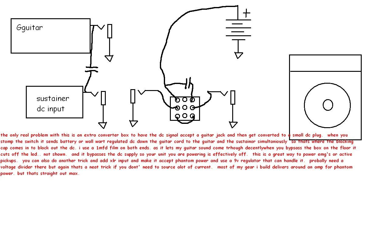
but... then you'd have a dc voltage coming out of the first pedal in your chain? couldnt you electrocute yourself with that? can 9 or 18 volts electrocute you? it seems like a good idea as long as it's safe...
-
Well, it's been almost a year since I covered this in my AP physics class but if I remember correctly, you cannot multiply two voltages together. You can only add voltages in series or add the reciprocal (1/V) in parallel (why parallel wired pickups are quieter than series).
Well that covers series and parallel connections, but I'm asking about a possibly different connection, probably involving a transistor or opamp, that does multiply the two together.
the idea i had originally was to connect one input to a transistor collector, and the other input to the base somehow. but the method in which you connect it gets pretty tricky. can anyone figure it out?
-
It almost sounds like you are designing a differential amplifier circuit or something like that.
A differential pair amplifies the difference between two input signals/voltages, and has an inverted and a non-inverted output. The DC offset bias on each input signal affects how the output waveforms look. That seems to be basically the same thing you are trying to accomplish...
seems like youre describing an opamp. but no, an opamp can only add/subtract signals together, then multiply them by a constant. that is different from multiplying the two together.
-
How can you multiply two voltages together? I'm working on a pedal that requires taking two input voltages and outputting the algebraic product of the two. This is not the same as multiplying a single voltage times a scalar value.
Also, is it possible to do the same thing, but with current instead of voltage?
I imagine either of them would involve using a transistor to have one input control the other, but I can't figure how exactly to do it.
For clarity, the device would follow: Vo = V1 x V2. Vo is the output and V1 and V2 are inputs.
It might also be helpful if someone has a method of dividing two voltages or currents.
I understand that there may be a problem with units; you would end up getting volts squared or amps squared. But maybe if there could be some sort of device that follows Vo = (V1xV2)/V3............
any thoughts on how to do any of this?
-
So, i'm sure this was answered somewhere in the past 306 pages, but I can't find it: is it possible to just use a cheap guitar pickup as a driver?
-
The answer is to add a thrid wire that connects only to the cover. So the phase switch is only reversing the coil and the other is connected directly to ground. Alternatively, you could phase the bridge pickup as this is the same effect...the phase sound will only occur when both pickups are selected...
pete
right. that way is much simpler than going get a multipole switch like i wouldve done. Just solder the metal cover straight to the bridge or something.
-
I put a humbucker in neck position of my telecaster and added a dpdt switch to go in and out of phase. When the switch is flipped and the pups are out of phase, I can touch a string to the metal HB cover and the sound goes dead. No output at all. In addition, you can scratch your fingers over the pickguard and get a noisy, static-y, scratchy sound which just doesn't work for me at all (to say the least). Switch it back and no scratchy sound. I'm puzzled.
What I wonder is whether the metal cover has anything to do with this and what can be done. All the wiring is correct so that isn't an issue. Any help would be greatly appreciated.
in normal wiring, the metal cover is assumed to be grounded. that way, when you touch the strings(which are also grounded) to it, there is no short circuit between hot and ground. That is exactly what is happening in your pickup. you touch the two together, and all the electric signal goes straight to the earth, through the strings instead of going to your amp.
one option is to make the metal cover isolated from both wires of the pickup, but then you lose the sheilding, and it gets a bit noisier. The other option is to rewire the switches so that when you phase switch the pickup, the metal cover gets connected to the other wire.
i dont have any schematics for that, though, you'll have to find some yourself
-
you can't really bend more than an eighth or quarter step before the strings roll over the fret edges
Have a look/lend an ear to David Gillmore. He does those 2 1/2 note bends and he probably cross several poles during those bends and you newer hear any volume drop or anything like that wehen he gets going.
I think you missed my meaning or I didn't phrase it properly. I was referring to the high and low E strings (where the bulk of the misalignment is), that one can only bend a very small amount (to the edges) before rolloing over the fret edges, meaning the edge of the fingerboard, where pitch usually jumps up some ridiculous amount, depending on what becomes the new magic fret surface when you lose the intended fret surface. I do realize the only way to get more than the 1/8 bend on these string is to bend them inward toward the center strings or center of the fretboard. For this reason, I would venture (and yes, this is totally speculative) that most players bend the high and low E strings toward the center of the fretboard, not toward the edges, except maybe for vibrato effect, if nothing else to avoid running out of fretboard. So, that being the case, it just seemed it would make more sense to place the poles for the E's where the strings most likely will be, not outside of them, on the fretboard edge, where most players do not want to go anyway (for me, out of fear of dreadful upward pitch shift upon fretboard rolloff).
right, you're supposed to bend pretty much all strings toward the center of the fretboard, or else you run the risk of going off the edge. i dont think the pickups were DESIGNED for going off the edge, they probably just make them a bit wider than they have to just in case they get misaligned a bit in assembly
-
Hello,
Thanks for that!
I've also got a reply via email by steven himself. He says the pickups will match allright, as the p-90 I have uses 44awg as compared to my 42awg. In the case of the pickups not matching by a mistake in either wiring or polarity, as you mention. Do the pickups sound correct when used individually? (switch on neck position or bridge position)
yes, individually, a reversed signal will not change the sound of the pickup. Unless you connect the pickup shield to one of the wires coming out of the pickup, in which case the wire with the shield on it must be the ground wire. And impedance matching is not important either, in those single-pickup spots.
-
Do you guys know where I can find them?
In the past, I've taken potentiometers apart and have been able to loosen them up a bit, but if there's a place that sells pots that are already "low friction', I'd just assume buy em from them.
Thanks.
I don't usually correct grammar, but it's "just as soon," not "just assume."
-
So over the weekend i wanted to play a bit on my guitar with the newly installed emgs 60/81.
Started playing with the 60 and it was clear and warm as always.
When i switched over to the 81 the 'volume was almost all the way down' so i turned the know up full volume and still just a faint sound was coming from the pickup when i played. turned it all the way down, still a faint sound coming from the pickup when i played... the volume knob had no effect.
baffled i took it to the pros on monday. checked all the wiring and everything that could be checked. Everything was fine. by this time the 81 was completely dead. We unplugged the the 60 and plugged it into the 81 jack and it worked 100%. did the same with the 81 and plugged it into the 60's jack, once again, no sound. the 81 was dead.
i just want to know if it is possible for the pickup to overheat or something, cause its still under guarantee and im getting a new one and i dont want it to happen again?
sounds like the symptoms of a dead battery. i mean, i'm sure youve checked something simple like that by now, but just in case you didnt, that's my opinion
-
Don't cheap out on the op amps and use something like a 741, go with burr brown opa627 if you can afford them. the opa 134 series is not bad as well and a lot cheaper
Amplexus
are you an advertizer or something?
-
Go down the radio shack and get you some tv antana wire that sould do away with the capacitance but you may have problems with hum.
J/K Sorry couldn't resist.
Grrrrr...
-
as long as the signals dont travel through the resistors anyways...
But the signal MUST travel through the resistors. When you say things like that, I get the feeling you don't understand the basics of electronics. The signal is applied as V2, V3, V4 etc as I said. Simple Ohms law tells you the signal must travel through the resistor to the (virtual) ground of the opamps inverting input. If it didn't, how would the opamp ever see it to amplify it?
wow, I just realized I should have worded that a bit differently. I know that the signals must travel through the resistors directly after their respective voltage followers, but I was saying that the signal from Voltage Follower A could peek throught resistor B and still effect opamp B, with the same principle as if there were no resistors.
I'm sure you can minimize that effect, but you'd have to choose resistor values carefully I guess.

Failed Headphone Amp
in Electronics Chat
Posted
i need to ask about why my opamp headphone amp doesn't work. and I drew up a scematic in MS Paint, but i first need to figure out how to attatch an image to this post. It only accepts URL addresses can someone tell me how to attatch the image?