


Mike Sulzer
-
Posts
221 -
Joined
-
Last visited
Content Type
Profiles
News and Information
Tutorials
Product Reviews
Supplier Listings
Articles
Guitar Of The Month
Links and Resources
Forums
Gallery
Downloads
Posts posted by Mike Sulzer
-
-
"So...I think you acknowledge that the magnetic field that dissects the string and the core is vital to the signal content of the vibrating string...yes?"
Are you saying that the magnetic field affects the vibration of the string? If so, i would answer "no, ideally the magnetic field does affect the vibration of the string." When it does, you have stratitis, or string pull. The plots that you show from FEMM show why a strat pickup would have more string pull than a P-90. The strength of the field is shown by how close the lines are together and how dark the color is. Note that the field strength is stronger over the Fender type pickup than the P-90.
The plots do not give a complete picture of the operation of the pickup. In principle you could complete it by placing a small piece of steel over the pickup (in the FEMM program) to represent the string. You could get the field and move this piece a bit, geting the field again, and subtract the magnetic fields to get the change in field that Peter's equation needs. A more practical method would involve using linearity, the fact that the total field is the sum of the steady part and the small changing part.
-
OK, I think that it is possible that there is some confuson about which magnetic field is under discussion. There are two:
1. the steady magnetic field caused by the permanent magnet and guided to the string by the pole pieces;
2. the time varying field caused by the vibrating string once it has been magnetized by the steady field from the pole pieces.
The field that matters in the equation for the ems is the varying field; that is why "change in magnetic flux" appears in the equation. The steady magnetic field does not enter into the equation, and so it has no effect. There is a changing magnetic field through all the turns of the coil, so they all contribute. But this field falls off with distance, so the top windings contribute more. The pole pieces help guide this field and prevent it from falling off too much.
The total magnetic field present anywhere in the pickup is the sum of the steady part and the varying part, as Peter said. But only the varying part contributes to the ems (signal from the pickup). But where the steady field matters is at the strings. The value of this steady field at other places is not importnat.
-
I agree with Mattia that epoxy (like System 3 Clear Coat) is good for brining out 3D on maple. I think it is also good at adding some strength, not needed on normal maple, but perhaps on some spalted stuff. Dye reduces 3D effects in general, but with care you can keep good 3D and increase the contrast. (I am not an expert on this, but I have been doing some fooling around on some pieces to figure out what to do on the real thing.)
Mattia: That padauk that i mentioned the other day as not having turned dark is now darkening noticeably. It just took a few months.
-
What do the magnets in a pickup do? They (temporarily) magnetize the strings, either directly, as in the case of a Fender type SC, or indirectly, by first magnetizing a pole piece (screw, slug, or whatever) as in a HB or P-90. In either case it is the magnetic material close to the string that does the work. The shape of the field down below away from the string has essentially no effect. That is, the permanent magnetic field passing through the coil is not the issue at all.
The other thing the pickup does is to sense the time-varying magnetic field that is produced when the magnetized string vibrates. Of course the coil is essential for this, but the pole pieces also play an essential role. This is because whether they are permanent magets or a temporarily magnetizable material like soft steel, they increase the tiny field fluctuations from the string that pass through the coil.
Try this some time: wrap several hundred turns of wire around a humbucker slug and connect it to an amp. Hold it over a pickup and string. See how much signal you get. Then try the same think with a plastic rod. The slug gives more signal because it amplifies the field from the vibrating string.
The third aspect of the pickup is the circuit it is in. The pickup has inductance, capacitance, and resistance, and other circuits, especially the cable capacitance affect its operation. Much of the diferences in pickup sound have to do with the frequency response of this circuit. In particular, a broad resonance is formed, and the location of the peak frequency and the width of this peak matter. This response is measurable. If you want to understand how much difference in sound between pickups is due to more subtle effects, you must first look at the frequency response.
-
I started with just a 1000pF - same thing, more treble as I rolled down the volume.
Added a 150K (I think that's the value I settled on) resistor in series with the cap, and now the tone stays pretty even all the way down.
i've read about Duncan and other folks' mods with the resistors in serries or parallel, but i'm trying to fine-tune it with just the cap--i'm happy with the taper on the pot, i only want to change the amount of high end that gets passed through. i bought a bulk pack at rat shack which included 221 and 561 pf, so i'll give them a shot.
The resistor in series with the treble bleed should limit the treble as stated above. It does not have a lot to do with pot taper. You might have to play around quite a bit to get the effect you want. Or you might never be completely happy even with the resistor.
-
Not too surprising that you hear a difference. But on the other hand the difference you hear is surprising me a bit.
The slug poles (as opposite to the adjustable, visible poles) have a slightly higher magnetic flux. Higher flux means higher output and more treble response. Flipping them would normally mean a tad more treble and that might be what you hear. A bit more “bite” so to speak. But sound is so subjective. What you feel is a decrease in “thinness” might be a loss in warmth to someone else.
Peter, I think whether the slugs or screws contribute the most signal depends on how the screws are adjusted. Adjusting a screw in general affects two things:
1. The strength of the magnetic field the string sees.
2. The sensitivity of that screw to picking up the fluctuating field caused by the vibrating string.
The two things together can make quite a difference.
-
I know I want something P90 style for my next project. Rather than spending a ton on the best P90's available, I'd like to expirement. The standard P90 seems about as complex as a humbucker (minus 1 bobbin of course). I'd like to try making a "P90", but constructing the bobbin like a Strat bobbin--two plates held together by fixed magnetic polepieces. No baseplate, bar magnets, spacers, etc.
I would probably design it to fit inside a standard P90 cover. Another thought is to use the top plate of the bobbin to mount the pickups "dogear-style". I.e., no pickup covers. The top plate would have dogears extending beyond the dimensions of the pickup hole and would be mounted with screws and springs. I would wrap the coil in black pickup tape like a coverless humbucker. Any thoughts on that? Is it a bad idea?
And has anyone ever tried a pickup like this? Just wondering...
The only physical problem that I can think of is that available magnets of the strat type might be a bit too long for P-90 case. But since you are not using a base plate this would just be a matter letting them stick out the back a bit and making sure you rout the body properly.
If you want a P-90 sound you need to get the resonant frequency right. I am not sure about the relative effective permeabilities of alnico magnets and the screws. I am guessing they are close enough so that you just have to make the coil with the same number of turns as a P-90 coil to get good results.
-
One question: Does a wood's tendency to damp or resonate certain frequencies contribute to what I would call "perceived" sustain? In other words, is it possible that what people are looking for is the increased perception of sustain, even though two different woods might vibrate for the same amount of time? Is 'resonance' the word we should be using instead of 'sustain'? That's more than one question, isn't it?
I think that is right. Often "great sustain" means "this really sounds good." The tone of a wood is largely which frequencies get damped fastest. Take two equal size blcks of wood, say maple and sapele (not really a mahogony). Both are bright, which means they are stiff and so resonate at a higher frequency than other woods. But they sound very diferent. The maple is sort of brittle, while the sapale is clean. Different frequencies last longer. Someday I want to quantify this with some measurements.
-
In addition to UV protection, I suspect that finishing has this effect: Since the pore filling/sealing allows the light to penetrate, it distributes the photons over a greater deph than in unfinished wood. That is, with unfinished wood, all the light energy goes into a very thin surface layer which is rapidly alered. With the finish, the energy is distributed over a greater deph, and so the final color takes longer to achieve. I do not know if this is what happens, but it makes sense.
Mike: good to know. I haven't got a lot of experience with the stuff, but the bits I have all went dark quite fast if left exposed to sunlight unfinished. Finish seems to slow the process a lot, but not indefinitely. May also be that some pieces just stay brighter than others, depending on the wood, the finish (epoxy can come with UV protection built in, ditto finishes)...but it is something to consider when bursting, I think. -
A few things to consider: you're working with a 'red' basecoat that's very likely going to be a dark reddish brown in a few years' time. Most padauk doesn't seem to hold on to its colour for very long, so keep that in mind, or let it pre-oxidise (sanded, leave it in the sun for a few weeks) to see what it's most likely to end up like.
Might look fine with blanks and browns, but it will be fairly dark guitar.
Mattia
I think it takes more than a few weeks. I finished an amp head cabinet in Padauk, and have had it sitting in a window here in the tropics for a few months, and it has not changed yet. I really like the way you can get different colors with Padauk depending on how you do the pore filling/sealing. With water base, it stays pretty light, almost orange. With System 3 clear coat epoxy it gets pretty dark right away. I think the epoxy really penetrates and allows the light to do so too, where it is scattered and so does not get back out.
Mike
-
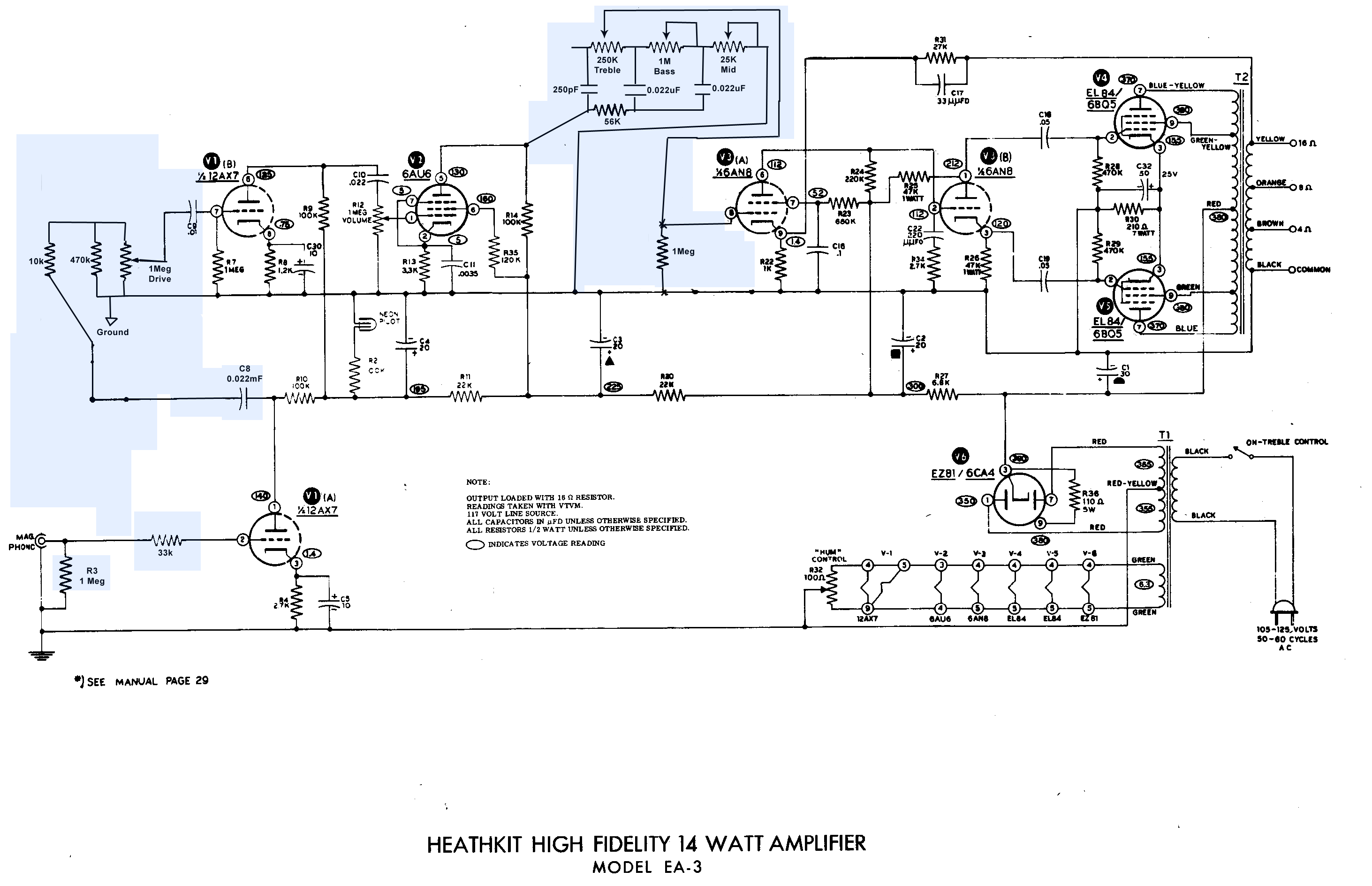
But remember if you connect the output tubes as triodes, you will lose a lot of power. The pentode connection connection using a resistor to the screen grid as described here seems to be the favorite way for a guitar amp.
Because the amp is cathode-biased, I believe it's "class A" whether both power tubes are working or not.Since only one power tube was conducting, you were only hearing half of the amp's volume potential (probably less). Before you buy a new tube, though, check the heater wiring at the socket of the dark tube. The heaters should be pins 4 and 5. If the tube heaters aren't hot, the tube can't do anything.
Be careful here - just because the amp is cathode biased doesn't automatically mean it's operating in class A. In fact given the cathode resistor in your schematic and where it's biased at (25V thru 210 ohms gives 120mA, each tube shares this at 60mA), I believe your amp is running class AB1. Given that the amp supposedly belts out "14W Hifi" it's highly unlikely to be running class A. The class of operation is a function of how "on" the tubes are under no signal conditions, not the fact that it's cathode biased. Check the datasheets for the EL84 for more info.
However Geo is right - it is self biasing and you won't need to worry about tweaking it when changing tubes.
You may find that your amp will stay pretty clean sounding right up to the point of clipping. The power stage is not likely to clip nicely as it is configured ultra-linear (pin 9 of each EL84 is connected to an extra tap on the output transformer). Most guitar amps run the output stage in regular pentode or triode-connected pentodes, ultra-linear output stages are pretty uncommon and are more a Hifi thing. This may be what you're after, but you could also consider disconnecting the ultra-linear taps and either running the EL84's as triodes (connect pin 9 of each EL84 directly to pin 7), or as regular pentodes (pin 9 is connected to the plate supply via a dropping resistor, say 100R-1K 5W - The schematic for the Vox AC30 shows the placement and value of a suitable screen resistor).
Some of these tweaks may make massive changes to the way your amp sounds, especially under high volume, so experimentation is recommended!

-
Mike - Your job sounds a bit funky.
What do you think about the cryogenic side of things? Can you shed any light on that?
I am skeptical of any process that claims to be a "miracle cure" for whatever is hurting. As for pickups, if you cool and heat them, I would be more concerned about what has changed in the magnetic material rather than the copper wire.
-
OK let's look at this from way back on the first page:
"What does happen when traditional single coils become overwound is response is slowed (because of increased resistance), bass response becomes muddy (because of increased inductance) and lastly highs become thin and bright (because of a decrease in capacitance). All of which are bad in terms of musical tone. It doesn't matter if you are playing 50's country or hard rock, a muddy bass and thin high end does not work."
Since this is pretty critical of what you say, here are my qualifications: I made by first pickup in the 1960s as a teenager. Same with amplifier circuits. I have a Phd in EE from 1979, and have worked as a scientist with high powered radars studying the ionosphere for 30 years.
Overwinding a pickup lowers the resonant frequency and lowers the Q of the resonance, that is, makes the resonance broader. The main sonic effect for me is a loss of high frequencies; you say different, but never mind that is just opinion in any case.
The real problem is that everything you say about the electronics is wrong. Inductance does not muddy the lows. An inductor has an impedance that increases with frequency so it matters more at the higher frequencies. The increase in inductance lowers the resonant frequency and causes a loss in highs. Also, when you wind more wire on a pickup it increases the capacitance, not decreases it. This lowers the resonant frequency somewhat, causing some loss of highs, but it is not a huge effect because most of the capacitance is in the cable to the amp. The main effect of increasing the resistance is to flatten the resonant peak somewhat (although it also causes a small loss in signal level across the band).
So if you do not bother to get the basic engineering right, why would you expect anyone to believe anything else you say?
-
Remember also that broken grounds can be a health hazard. As Curtisa suggested, start by checking the "third prong" connection to the chassis. Do it soon.
My amp (fender frontman 15) just started to get a really bad hum to it today. Ive played 3 different guitars through it so I know the guitar isn't the problem, and 2 different cables so I dont think its that either. I noticed that if I touch the metal part of the handle and my guitar strings at the the same time the humming stops. Any idea on how to fix this? -
R32, hum control: The AC on the heaters and heater wiring can be "picked up" by other parts of the circuit. The purpose of the pot is to balance it out. The idea is that one side of the heater circuit is positive and the other part negative with a net effect near zero. The pot is a bit surprising; most amps just use a pair of fixed resistors. Further hum reduction can be achieved by connecting the "center" (the pot slider in this case) to about plus 70 volts rather than ground (although it should be AC bypassed to ground with a capacitor). This reduces the hum pickup inside the tubes.
I will give it a look, and see if the heaters are live. The tube in there didn't seem to heat up at all. First, I think I may try switching the tubes, to see if the problem lies inside one of the tubes.I will take your expert opinion that the amp is self-biased, and/or Class A. I was fooled by the potentiometer on the amp, which I mistook to be a biasing pot. Looking at the diagram, it appears the only thing it could be is a "hum control" pot. What exactly does that fancy hum control circuit do?
Your amp is cathode biased. R30 and C32 (between the power tubes) automatically bias the power amp, so all you have to do is put in a new tube (no need to adjust anything). Don't worry about matching them. Mismatched tubes may make a more "musical" guitar amp.Because the amp is cathode-biased, I believe it's "class A" whether both power tubes are working or not.
Since only one power tube was conducting, you were only hearing half of the amp's volume potential (probably less). Before you buy a new tube, though, check the heater wiring at the socket of the dark tube. The heaters should be pins 4 and 5. If the tube heaters aren't hot, the tube can't do anything.
-
Your amp is cathode biased. R30 and C32 (between the power tubes) automatically bias the power amp, so all you have to do is put in a new tube (no need to adjust anything). Don't worry about matching them. Mismatched tubes may make a more "musical" guitar amp.
Because the amp is cathode-biased, I believe it's "class A" whether both power tubes are working or not.
Since only one power tube was conducting, you were only hearing half of the amp's volume potential (probably less). Before you buy a new tube, though, check the heater wiring at the socket of the dark tube. The heaters should be pins 4 and 5. If the tube heaters aren't hot, the tube can't do anything.
Could just try interchanging the output tubes, briefly. You can have class AB with cathode bias, but I think it is better with grid bias. The problem with cathode bias and only one tube working is that the current through the working tube is higher than normal and the extra dissiaption could shorten the life of the tube. So you should get both working.
-
Good, I was hoping you had a metal covers. Sometimes unshielded pickups such as Fender-type single coils can be a problem when switched in this way.
And Mike, both pickups do have metal covers, and when I tested the guitar it was almost completely silent. Noticably quieter with the distortion on than the store-bought guitars I have. -
Ben, the circuit looks like it will work to me also. The only thing that is perhaps not good practice is opening the ground connection of a pickup to turn it off: this might increase the hum pickup. But if you can ground a metal frame, it could be OK.
Parallel humbucker connection is frequenctly used. It gives about the same level as a single coil as I think you know.
-
Geo is right. It does not need that cap, and there is no effect on the tone. I misunderstood the schematic.
So is the tone stack cap in or out? If I leave it out, is the amp in any danger of blowing up or melting down or teaching children dirty words or something, or is it more of a tone consideration?I think the purpose of the .047 uf C before the tone stack is to keep the dc out of the pots. i would put it back in.I believe the 250pf, .02uf, .02uf of the tonestack will do that. The tone stack in a typical blackface Fender has no cap between the plate and the tonestack input, for example here.
http://el34world.com/charts/Schematics/fen...VERB_AA1164.pdf
-
I think the purpose of the .047 uf C before the tone stack is to keep the dc out of the pots. i would put it back in. At some point you might try removing the feedback from the secondary of the output transformer. This makes the onset off overload more gradual. It is up to you how it sounds best.
Heres Draft 3:This incorporates all the fixes (I think) that you put in. However, the text on your schematic was really small, so I had to guess at some of the values, and I couldn't tell what the text at the 1Meg resistor near the 4th gain stage said.
Thanks again for all your help!
-
Yes, you can change the input impedance, throw out the RIAA, and put in a bass-mid-hi tone circuit. You might also want to change the values of some coupling capacitors. A guitar output is quite a bit higher than a good phono mag cartridge, but that is OK since you want the extra overload capability. You might also want to add a gain control (that is, have two "volume " controls, one early, the other late, in the preamp, so that you have independent control over how much preamp distortion you have.) But if you feel confident in making those changes, go for it. Guitar amps are intended to survive when played overloaded forever. A cheap hi-fi amp might not last, but it might have a good enough power supply.
I am aware of this. However, after looking at the circuit diagrams, and reading around on the website, it appears the main difference between an amp capable of amplifying a magnetic phonograph input (similar level to guitar input), and a guitar amp is the tone circuit. The hifi amp uses RIAA equalization and a tone circuit that covers the whole audible spectrum (i.e. 40Hz - 20,000Hz), whereas a guitar amp uses a flat equalization and a tone circuit that only covers the guitar's range of sounds (80Hz - 2,000Hz or so). So in theory, replacing the tone circuit and the input jack should be all I need to do to change the amplifier into a guitar amp (given that I don't need crazy mesa boogie distortion or anything fancy like that).As for buying a cheap guitar amp, the cheapest tube amp I have seen is the $149 Epiphone Valve Junior at 5W Class A. I can get a quite decent 14W mono "Hifi" amp for $30-$60. A tube amp of equivalent power is about $300 (Epiphone Blues Something-or-other). Sadly, the prices for used guitar amps aren't that much better than for new amps, and the older the amp, the higher the price! With the $100 I save with a hifi amp, I can buy myself all the materials I need to build a nice little speaker cab, and the components for a new tone circuit.
-
The preamp for a guitar amp is different than for a hi-fi amp. There is no reason why you cannot convert one to the other, but one would need to work with the circuit to see what to change. I think it would be easier to build a guitar amp from a kit than to convert a hi-fi amp. Have you looked at the AX84.com site? Or search for guiatar amp kits.
I'm considering building a tube amp as a project. I'm a decent woodworker, and have SOME electronics experience. I wire my own guitars, and have built a few effects pedals. Seeing as I'm no electrical engineer, and since tube amps have a tendency to store large amounts of electricity laying in wait for the uneducated technician's fingers, I thought it might be a good idea to buy an enclosure-less amp from eBay and build my own cabinet. Looking at the prices, I see that tube amps from record players or PA systems are much cheaper than dedicated guitar amps. After doing some research online, I have found many websites with different opinions on what is necessary to convert such an amp for guitar use, and how the resulting amp will sound.Anyway:
1. Is it a realistic goal to convert a "HiFi" tube amp into a guitar amp?
2. Is it necessary to modify the amplifier's circuitry to achieve a decent sound?
3. If it is worth it to do this conversion project, what features should I look for in a "HiFi" or PA amp that would make it good for this project?
4. I'm looking to build a practice/very small gig amp, I am assuming that means 15W - 30W. Is this a good power level for that goal?
5. How difficult would it be to add a 3 band EQ to the amp?
Thanks!
-
One more thing about the dc resistance. Suppose we wind two pickups, one out of #42, and the other out of #43. Suppose we use the same number of turns, and the coils have the same shape and size. (Perhaps we could find #43 wire with thicker insulation so that the total diameter of the wire, copper plus insulation is the same. Also remember that the inductance of the coil is affected by the shape since how the turns couple together is important, so for comparison in this "thought experiment", we want the coils to be as much the same as possible, only the resistance different.) So we have two coils, the same except for the resistance. The electrical responses will not be exactly the same, however. This is primarily because of the effect of the resistance on the resonant response. The inductance of the coil and the total capacitance from the coil and the cable make a resonant circuit, that is, one that tends to have a peak in the frequency response. With the lower resistance (#42) the peak is somewhat higher and narrower in frequency that with the higher resistance (#43).
-
The question has come up on other forums and no one has even had any ideas that would stand up to discussion, not to say actually work.
Seen the question at least half a dozen times, and it's never resulted in a supplier being identified. Me thinks that speaks volumes...

Designing A Pickup
in Electronics Chat
Posted
"Wouldn’t that mean that the magnetic field strength (flux) at the bottom of the coil play a role in the sound/output of a pickup?"
But let us look at where the flux is changing the most. The string gets magnetized over the pole piece. The field from the "string magnet" is strongest at the string and decreases as you get farther away. The pole piece modifies this field, slowing down the rate of decrease somewhat. The magnet below the coil has some effect, too, due to its magnetic permeability (that is, this field applied to the magnet causes small changes in its internal magnetic alignment). When the string vibrates, the changes in the field follow this same pattern, stronger near the string, weaker farther away. But the field from the permanent magnet is not part of this change. It did its job in magnetizing the string.
So in the equation you have the term d(phi)/dt. This says "rate of change of the magnetic flux". The magnetic flux is magnetic field through the coil times the area of the coil with allowances for the spatial variation of the field. So the ems (voltage) across the terminals of the coil depends on the rate of change of the flux. It is the sum of the voltages induced in each turn of the coil (series voltages add). The voltage from each turn depends on the change in flux through that turn. The flux changes most near the string. The part of the core closest to the string has the most effect modifying or amplifying the changing flux, and the magnet below has less effect.