


col
-
Posts
628 -
Joined
-
Last visited
Content Type
Profiles
News and Information
Tutorials
Product Reviews
Supplier Listings
Articles
Guitar Of The Month
Links and Resources
Forums
Gallery
Downloads
Posts posted by col
-
-
hmm one of the best ways to get a 'thicker' sound from a delay (or chorus type of) effect is to use a stereo one and feed two amps in different positions.
To do that 'on-board' you are going to need a stereo lead from the guitar - yet another reason why off-board is better.
Personally though, I would say that if you 're not happy with your sound, get the basics right:
playing skill, guitar, pickups, setup, strings, lead (yes really) and amp are most important by far - if you're not getting close to what you want with just these, then no amount of effects will magically fix your sound.
Learn how to get a sound from an amp - it's surprising how many people fail to get the best from their existing kit.
After that, the thing that to me is by far the next most important thing is the right booster to drive the amp. e.g. rangemaster clone, tube screamer etc.
And (you probably know this already) remember that what sounds thick and wholesome when practicing in your room can turn into a big muddy mess when playing in a band situation.
Remember, it's your 'sound', and don't worry if others are criticizing you for not having some piece of kit - if your sound is killer, they will quickly shut up. And if it's not killer, then you need to work on the basics.
-
but from a purely fundamental standpoint, it seems like it would work.
Assuming you can get around the current requirements, the need for a very clean power source (any slight noise will be overwhelming in the pickups output signal), and the physical bulk of the coils for your electromagnets, what about the properties of the transformer you will have just created that is generating meltingly large voltages in your pickup coil ?
-
so would it do any harm to mess with he resistor i highlighted with the screwdriver? it boosted the volume like crazy? how would i go about it?????
I would leave it alone. From the pic you posted, it looks like the 1k resistor on the output of the op-amp. Messing with it will probably change the tonal characteristics, output level and overall response of the unit (in a bad way). It's usually safe to assume that the folks who designed it knew a whole lot more about electronics and guitar FX than you do, and that they chose the correct component.
If your Rat is one of the early ones with no LED, then the easiest option would be to swap the RAT's 2P2T switch for a 3P2T switch, and wire up an led to the switch - like in the page Borge posted (post 2 in the thread) - this is assuming that you can fit a 3P2T switch in there.
(If you can't understand that diagram and how it could be installed in your RAT, then you probably should just leave it as it was, before you break it. At least until you have learned a bit more about electronics and reading schematics)
cheers
Col
-
nice coil building method

-
If my memory serves me correctly, the RAT was the inspiration for the development of the 'Millenium Bypass' allowing cheaper components to be used while still providing true bypass and an LED indicator (without the circuitry, you would need a 3PDT switch instead of just 2P2T)
Search 'Millenium Bypass' and you'll probably find some discussion of the RAT approach and how it works.
EDIT: looky here
cheers
Col
-
Some stability issue, keeping the load impedance low and real: Boucherot cell
Cool, I'll check that out (again) EDIT: that makes sense,
More like this: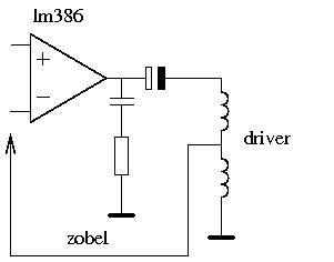
cheers
FF
That looks(?) like a current amp to me (assuming the in signal goes to the LM386 +ve input and the feedback line goes to the -ve).
this is a very good article on the subject.
I messed about with this idea in simulations taking the feedback to the LM386 input with poor results.
Then after a look at the internal diagram of the LM386 in the datasheet, saw that I could take the feedback directly to the input of the push-pull stage of the LM386 via pin 1. This worked very well in simulation, and the test circuit I built seemed to work fairly well, but I still don't have a scope, so haven't been able to test it thoroughly enough to be confident about committing to it.
Here's the basic idea:
You would have to either low pass filter the input signal, or stick a cap and resistor from pin1 to pin 5 to low pass the amp. otherwise frequencies above 2k or so will cause clipping as the peak to peak voltage required to maintain the current is too much for the LM386 with a 9v supply.
EDIT: or of course, use a 'boucherot cell'.
You could use a coil tap instead of the 0.1ohm resistor, but I think you would get into trouble with precision issues, and you would gain so little in efficiency that it's not worth the hassle.
I can't remember if I ended up using an 0.1 resistor or slightly bigger... it was very low resistance anyway.
A variation of this might work quite nicely as a Ruby style amp going by that esp article - he talks about using the approach to get closer to the response of a valve amp!
I'm afraid the criteria has and been repeated for many years...The so called "secret circuit" ... 8< snip
It's simple Pete, I'm annoyed because you claim to have made your specs public. This frustrates me because it is misleading, and may have an impact on anyone new who comes here and tries to build a sustainer - I explained why in my previous post.
You don't seem to have a straightforward answer to this, so I'll leave it there for now in order that we can try to keep things on topic.
Cheers
Col
-
Point taken FF, my only real query about the drivers is that is there a difference in the values of things such as the zobel with different output caps or indeed radically different loads...ie drivers. So, what may be expected to work with one type such as a dual coil system like yours or cols...may not be the same for single coil drivers such as the ones I typically use and is most commonly made.
A has been explained MANY times before, the 'load' from the driver depends on the combination of its inductance, its DC resistance and the signal frequency. whether it has 1, 2 or 74 coils is irrelevant. A zoblel that works for an 8ohm 1mH single coil driver will work just the same for an 8ohm 1mH dual coil driver or an 8ohm 1mH 17 coil driver made from unobtanium by aliens from uranus.
In this regard, for years my criteria have been publically listed...Again as has been mentioned many times, this is NOT TRUE.
You have never posted a diagram of your driver circuit. This is significant, because its amplitude and phase response will have an impact on how different output caps effect the overall result.
e.g. It may be that a 100u cap works for you precisely because of an unusual phase or amplitude response from your driver circuit.
IMO, you should be clearly stating this as a caveat when you recommend various selected component from your system. Unfortunately, in this case, you seem to be doing the opposite.
You are very quick to criticize the abilities of "the kinds of posters typical here".
"I do think though that they need to be developed further and a 'formula' presented as to how to build the things before I personally advocate them to the kinds of posters typical here. I understand you new directions, but I don't know exactly what you would be advocating for people to replicate your results, particularly with the skill set and expertise that seems evident"
Maybe the real problems is that they are doing a great job building adequate drivers, but having no ultimate success because, crucially, the driver and output cap are only one part of the system, and the rest is just as important and in your case is *secret*.
I for one have tried a well built 'to Pete's spec' driver with a fetzer/ruby, and I can tell you the results are not acceptable to me.
Your normal response here is to state that you don't and never have recommended the Fetzer/ruby... but this time before you do, maybe you should consider where that leaves folks who want to follow your philosophy that a sustainer needn't be complex and that fancy AGC circuits are not necessary... that's right, it leaves them with no alternative to the Fetzer/Ruby!
cheers
Col
-
I do wonder though the influences of the drivers as well, both FF and cols are dual coil systems and I expect quite different from the simpler single coil drivers I have generally used.
you expect quite different what?
I noticed quite a bit of difference with things like both my bi-lateral and compact rail drivers...seemed to need to be extremely close to the strings in comparison and not to drive things as hard though the circuit and guitar remained identical.Did you design the bi-lateral and rail drivers carefully so that their permanent fields were of similar strength in the area around the strings, and so that they had the same overall inductance as the single coil you were comparing them with?
If you didn't, then your comparison cannot tell you ANYTHING about the relative merits of single coil, bi-lateral, or rail drivers.
I could easily knock together a single coil drive that work much less well than my rail driver - equally, I could make a rail driver that works less well than my single coil.
If you were trying things out without taking measurements (DC resistance doesn't cut it I'm afraid), then your results cannot be used to generalize beyond those particular drivers.
cheers
Col
-
You got me thinking. Have you ever thought about an ultralinear like design? Create a negative feedback loop with a tap on the driver coil.
Do you mean a 'current mode' amp? with a 'current sense' resistor between the driver and ground to provide a feedback current?
I have attempted this, but I tried to do too much in one go (I messed around with driver specs at the same time)... So it's still to be tested properly. I attempted it feeding a very low current back through pin1 of the LM386 via a decoupling cap.
cheers
Col
-
Yes, but the same input signal doesn't distort more with a 16 ohm load. There is only less efficiency with a 16 ohms load. It works the other way around, the bigger the load impedance the more headroom. More voltage but less current.
That makes sense, but then why does a zobel network help ?
What is it about the amp that requires it to feed a resistive load?
cheers
Col
-
1. Firstly, is it really necessary for me to go make a new bobbin and wind that up etc, or could i manage with what i have?
Where did i get this idea from? well it's nothing major really. If the coils that i have seperated already have pole pieces running through them, could i just seperate them (so they're 2 single coils instead of 1 humbucker) and then attach the magnet back to one of the coils, so the pole pieces become magnetised, or does the magnet HAVE to be inside the coil? My idea behind this was to just have the one coil being used as the driver, and then with the other one, leave it there, but have it grounded so that it'll fit neatly into a humbucker sized route.
Use one or both coils as driver (I'd go with two). As long as the inductance is around 1.2 mH and the resistance is about 8ohm.
So if you're using two coils, you want either two 16 ohm 2.4mH coils in parallel, or two 4 ohm 0.6 mH coils in series.
2. Has anyone tried this with the coil being perpendicular to the strings?If my electromag theory is correct (haven't done physics in 4 years, so it could be wrong) but wouldn't that make the flux stronger??
not quite sure what you mean - all the diy sustainers I've made and seen have the driver field perpendicular to the strings.
It'd be such a big help if i didn;t have to go out and buy stuff for this. I've all the necessaries for the preamp etc, but the driver is going to be the tricky part i think.it's all 'the tricky part'
Col
-
I meant, does the output cap have an effect on the zobel calculations you present?
No. The response of the Zobel will be the same, however, changing the output cap will change the overall response, so depending on the value, one might want to tweak the Zobel response to compensate.
With much bigger caps, the high end can struggle (the source pickup can have a difference though to the high end response of course).No, you have this upside down. A bigger cap will have no effect on the high end. It will however help the low end, so if you don't have AGC, you have to turn the gain down because the low end is too strong, this compromises the high end. If you have a functioning AGC, this is not an issue!
so a basic buffered LM386 but when the output across the zobel network exceeds a certain level, it triggers a diodes threshold and turns off the input. Some capacitors slow down the rate at which the source signal is turned on. All of this then is attached to the zobel network effectively I suppose, but only when the thing automatically turns off for a bit. If the level of the strings still vibrating through momentum is still too high, the thing will remain off by recharging the caps for another cycle. If the "drive" control is set to a very high level, it would appear that this cycling is effectively defeated or too fast to have any appreciable effect, at lower levels more so. I had considered that perhaps a similar mechanism could be used to switch through different output caps or be frequency sensitive and therefore "fix the feature" of low string harmonic bloom in the fundamental mode...Sorry, Pete, but none of this makes any sense. You seem to be trying to describe some sort of AGC, however, if you had a working AGC, you wouldn't need a 100u cap to even out the response.
Also, a Zobel is an impedance adjustment network, if you start attacking feedback lines from it, its not a Zobel any more, so to call it one is misleading.
You aren't going to be able to 'fix the feature' of low string harmonic bloom until you switch to a bigger output cap. A 100u cap favours the harmonics of the lower strings by something like 10db over the fundamental. To 'fix' this you need a level frequency response, and AGC to even out the amplitude response.
...Again, it is a credit to the LM386 how easy these things are to work on that you can do stuff like this, output caps, zobel networks and AGC's and such can be constructed to suit pretty easily even with 'doofus' methods like mine.
It's no credit to the LM386. A Zobel can be added to any amps output. Unfortunately, the response of the LM386 is so sensitive (bad) that a zobel is essential. AGC can also be applied to the input of any amp.
I'm not sure about your circuit because I haven't seen it, but from the descriptions, and things you've said about the way it sounds, there 'aint any AGC happening in there - you wouldn't be getting the best response with a 100u output cap if you had functioning AGC. EDIT, I'm not saying that it doesn't work, or that your feedback circuitry doesn't help, just that it isn't AGC (at least in the usual sense of the term).
I am not sure how important it even is for people to drive the fundamentals either you know......but it is also cool to hold a chord, play the higher strings, clean and natural without sustain and have the lower notes gradually morph into harmonics above the chord.Yes I said as much in my post. However, it is also cool to strum on a low chord and for the low notes to be driven as fundamentals, but the high end to bloom to harmonics, so you end up with a deep fundamental bottom end simultaneously with high pitched harmonics. My system can do this, but it's not possible without a 470u output cap and AGC.
I also get reasonable sustain of clean chords, but I can switch to blooming harmonics if I want.
cheers
Col
-
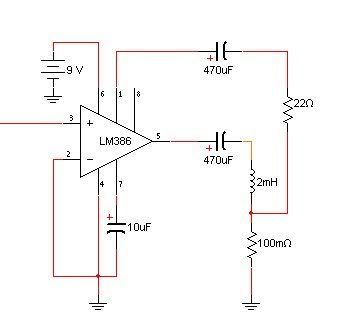
...plus the 100uF cap that also bridges from pin 5 to the output...I wonder if the value of the outpuct cap has a difference as well...
Of course the output cap makes a difference.
For a level impedance, and a flat frequency response, you need at least a 220u output cap, but a 470u will give flatter amplitude a phase response at the low end of the guitars range.
The reason you have found the 100u to be successful is related to the fact that your AGC is maybe not doing an aweful lot.
Assuming an 8ohm driver at about 1.2mH, a 100u cap causes the output to drop off below about 330Hz, which is the high E string frequency. The response stays flat up to about 600Hz, and drops off above that.
So what it is doing for you is providing more drive at the 'difficult' frequencies, and less where for various reasons the sustainer works more easily. This sounds great, but there is one problem - although I know you think of it as a 'feature' - frequencies lower than 300Hz or so will not be driven as fundamentals, they will bloom to harmonics. This is because the 100u cap favours the harmonics because it acts like a bandpass filter pushing 300Hz to 600Hz.
It's not a big problem really, the sound of the lower notes blooming to harmonics is natural and similar to what a loud overdriven guitar does anyway. The only other downside I can think of is again the issue of impedance. The drive drops off below 300Hz because the capacitors reactance causes the impedance to rise. This has the potential to again cause problems with the LM386.
I guess that the strange 'modified zobel' setup you have talked about with some sort of feedback might be in some way counteracting this... dunno as I've not seen a schematic. Anyhow, it might be possible to create a very basic sustainer with fairly even response by using a 100u can and having a zobel to counteract the rising impedance at the top end, combined with a chunky inductor to perform the same role for the low end.
AGC will give more control, as you can drive the fundamental of all strings, but for those who want a simple circuit to build, this might be something worth looking into. (the G string will be VERY lively though, as it can be driven easily, and it is not attenuated much by this approach.
cheers
Col
-
Just a quick 'heads up' for folks messing around with LM386 based sustainer projects (eg. Fetzer Ruby).
The Zobel network in the LM386 datasheet uses a 47n cap and a 10ohm resistor. These values are necessary because the circuit it is intended for full range audio - songs etc. The downside of this is that it doesn't do enough to offset the problem of inductive reactance rising at higher frequencies in a sustainer system.
Explanation:
Assuming a driver with inductance of around 1.2mH (the basic design as developed by Pete), even with the datasheet zobel network, the impedance at 2.5kHz is about 16ohms, at 5k it's more like 40 ohms.
Look at the graphs in the datasheet, you can see that the maximum power available before the distortion (THD) gets high gets much lower as the impedance rises... with an 8ohm load, you hit 10% THD at about 0.75W, whereas with a 16Ohm load, 10% THD comes at about 0.45W.
This becomes a problem as soon as there is clipping in the signal chain - clipping generates high frequencies in the signal. With a standard zobel network, these will cause nasty distortion a plenty from the LM386.
Solution:
Change the values of the zobel components.
We don't need to drive anything like the full audio range, we only need from 82Hz to say 1.5Khz. So if we change the values of the resistor and cap in the zobel to 8ohm and 10u, we don't lose anything we need, and as the signal rises to the point where the inductive reactance of the driver causes the impedance to rise to distortion levels, the zobel provides an alternative route for the current So that the LM386 just sees a nice friendly 8ohm impedance.
The result is that if you drive the circuit hard, instead of a really nasty fizzy distortion, you get a more musical rumbly crunch type of thing (at least I do), so if yo are having trouble with fizz, this might help a bit.
remember, Zobel values: cap 10u, resistor 8ohm.
cheers
Col
-
Re... adjustable pole pieces. The reason I asked this question was because some people had recently posted about drivers which used pole pieces:. ..specifically Elmo, and Hank.
It seemed to me that the common problem of uneven string response could be alleviated by varying the pole-heights. I guess that my armchair logic failed again! I see that if I had thought it thru I would have realized: if that were the case then varying the pole-height of the pickup pole would have the same effect. But alas, I know that doesn't work.. .. for the reasons Pete pointed out.
I know many have built successful AGC into their circuits and achieved an even string response. (Latest clips by Fresh Fizz were great!) But I didn't remember reading of someone who actually tried varied pole heights.
Anyone tried a multi-band Equalizer between the driver signal and its amp?
Thanks ALL for the awesome discussion!
I guess the main thing to remember is that the effect will probably be slight, e.g. often the G string is a bit too lively. You would probably need to take the pole piece under the G string down a lot to get it's response even with the B and E strings.
Thinking about it from another angle, the field from the sustainer driver will still be pretty good even if you remove the core completely (maybe 60% of its strength with the core). The significant thing may be the permanent field. It might be that there is a fine line between plenty of domain alignment and not enough, so to tweak the response in a finely grained way by adjusting poles may be tricky. This would be due to the fact that the field drops off with the square of the distance....
It's hard so say for sure, but intuition suggests that adjusting the balance of the permanent field might yield more obvious results than trying to tweak the field generated by the coil. Worth experimenting with though.
Col
-
oops, forgot to add that of course, the physical phase gap between driver and pickup will also play a big part in this process - as the harmonic frequency rises, the pickup/driver gap becomes a bigger proportion of the cycle.
-
The basic harmonic mode using a 180º phase inversion by swapping the wires is a little bit more complicated than most people give it credit for.
Think about it:
if you invert the signal, the driver cancels the fundamental, pushing the octave harmonic.
BUT then surely the octave harmonic then becomes the signal to the driver, and is in turn cancelled...
YES, otherwise the harmonic mode would stick at the octave.
BUT then surely if each time around, as soon as the next harmonic blooms it is cancelled, we soon get to such a high note we can't hear it?
AHA! that doesn't happen! WHY?
Now we are getting somewhere.
What is really happening - I think - is that the 180º phase shift is 180º across all frequencies due to the way it is obtained by swapping the connections. However, the drive circuit and combination of output cap and driver coil have a phase response that, while fairly flat over the desired range (82Hz to about 1200Hz), will quickly start veering off as the frequency increases. The note that the harmonic mode settles on is defined by the point at which the phase response of the circuit/cap/driver is more than 90º (and less than 270º) making the overall phase sum less than 90º (or greater then 270º).
This means that unfortunately, if you have a circuit with a very flat phase response (good for efficient sustaining) like mine, then the harmonic mode will generate unpleasantly high pitched harmonics, or ones that are so high, it can't drive them.
I think that one good way to create a controllable harmonic mode might be to in some way control this 'tipping point' where the response of the system cancels the 180º shift and halts the bloom effect.
What is the best way to do this ?
I don't know, but it isn't an approach that I have messed about with.
I did have some success with an all pass-filter, and a simple high pass filter, but I haven't yet managed to do a controllable effect where you can immediately notice the difference when you turn the knob... maybe a resonant filter will do it, or maybe tweaking the phase response in combination with a 180º shift will... (maybe a resonant filter is the best way to tweak the phase response...)
cheers
Col
-
Say, high strings are much harder to drive, so, seemingly, the high string coils must produce stronger magnetic field (the signal one, of course, not permanent). You can tweak it with amp gain, but you can also try to optimize the coil parameters for different strings. I have a suspicion that high string coils must be bigger, have thicker wire, while preserving about the same DC resistance. Is that correct? Once again - it's only a matter of optimization, nothing more.
If you use thicker wire wound to the same DC resistance, that means many more turns, so a much higher inductance value - as I explained, this will act as a low pass filter, meaning that response on the higher strings will be very poor.
For driving the higher strings, you need to keep the inductance quite low!
As far as I can tell, there are a few ways of maximizing the drive that will work on the high strings.
#1 more current
#2 a more focused field
#3 choose an output cap that combined with your drivers inductance provides minimum impedance at the weakest frequency.
#1 could be provided by a class-d amp, but I've not gone there yet. #3 I have done. #2 is what I'm intending to have a go at, but don't hold you breath. RealLife™ is very busy right now.
My idea for #2 as I have explained is to have two (or more) coils, one large one that has a high inductance and drives all strings. one small one that has lower inductance, but is only stretched over 2 or 3 strings, so its field is more focused. That's the plan, not sure it will work though, and I need to order parts before I can even think about implementing it, so I'll probably play around with variations of the design before committing to one design.
Other things that should make a difference:
Make sure that the action is as low as you and your guitar can stand - particularly at the nut.
Try different brands of strings, try heavier strings.
cheers
Col
-
I'm thinking...say you wanted this value for a single string driver...this calculation seems to be for a 55mm full coil...so, for a single string you would need say a 5mm coil and given string spacing of 10mm, then there is only 2.5mm to wind on...so how deep at theses things if you have to put that kind of wire (o.27) and what effect would this have...
You are totally missing the point of my post Pete.
I am explaining the process you need to use to work this stuff out. I used a 55mm driver as an example because thats what I have measurements for.
The same process will work in the same way for a single string driver, however, the OP would need an inductance measurement from a driver with known number of turns as a starting point - I explained this in my post, and that a 'good enough' inductance meter can be had for very little money.
cheers
Col
-
BTW, Col and Psw, based on your great experience, can I ask you to roughly estimate parameters, optimized for each string, considering different frequency ranges, different string thickness, and assuming that the driver consists of 6 independent coils, driven by 6 power amps and a true hexaphonic pickup (exactly like in the Moog guitar). I'm not suggesting you to build this "nightmare", I'm just looking for a starting point for my experiments.
That's pretty difficult, because so much depends on the physical layout and the cores you use.
If you take two single string coils that are each 1mH when alone and place them next to each other, the effect of mutual inductance with either increase or decrease the effective inductance of each coil (depending on if you have them in or out of phase with each other). How much they effect each other depends on proximity and, (i suppose but am not _sure_) how much of the inductance is being created by the core material.
As far as what inductance would be optimal per string, you can work that out for yourself. There are a few online calculators that can help a lot.
pickup calculator can help you work out roughly what wire gauge you would need to get a desired DC resistance from a particular number of turns.
the Inductance Calculator here can help you work out what the impedance will be for a particular driver (assuming you can calculate or measure roughly what the inductance is)
the RLC calculator here can help you work out what response a particular combination of cap and inductor (including the DC resistance) will give you... so do some research to find the frequency ranges of each string, then use the calculators to work out some ballpark figures to get started with your experiments.
To get you started, a 55mm driver wound with 150 turns of 0.23mm wire wound round a thin steel core gives and inductance of roughly 1.2mH. You can use the relationship between number of turns and inductance to calculate rough inductance values for similar drivers with more or fewer turns:
e.g.
how many turns would I need if I wanted a 3mH driver ?
150^2 = 22500 (inductance varies with square of number of turns so square our initial number of turns)
22500 / 1.2 = 18750 (we know 1.2)
18750 * 3 = 56250 (we want 3.0)
sqrt(56250) = ~237 ( square root gets us our answer)
so using the same core, I should get near to 3mH by winding 237 turns instead of 150.
now, assuming that 8ohm is what we need in this case (it might not be, depending on the drive circuit) what wire would get nearest ?
using the pickup calculator, we find that 237 turns of 0.275 (SWG 32) wire gives 8.2 ohms which is close enough
Of course, for this to be useful, you need some way of measuring a baseline inductance for your driver wound on your core material. Cheap inductance meters can be had for less than £20, and although not high precision, are plenty good enough to guide this kind of process.
good luck
Col
-
3.anyway,i got a TA8210 based circuit,the power is crazy,20 watts,and it can take loads of 32 ohms,to be honest i have tried it,i run it on 12volts 2 amperes adapter and use 32ohms driver...it works no doubt...all 3 low strings has moved even before i touch it....but yet the high frequencies response not that good
32 ohm, but what inductance ?
For a driver with a ~55mm long core wound with 0.2mm wire to be 32 ohm, you would need roughly 470 turns.
A few basic rules:
inductance increases with the square of the number of turns, so if 120 turns gives 1mH inductance, 475 turns will give about 15.5 mH
In the same way that capacitors act as high pass filters, inductors act as low pass filters, the higher the inductance, the lower the cutoff point.
e.g.
at 660 Hz (12 fret high E string), an 8ohm 1mH inductor (driver) will have an impedance of about 9ohms
a 32 ohm 15.5 mH inductor will have an impedance of 71 ohms
What this means is that you need to be very careful about how many turns of wire are on your driver. Too few and you won't get enough drive, too many, and the higher frequencies will be wiped out.
For a 32 ohm driver to have a low enough inductance, you would have to use very thin wire. this would not be able to carry the current you are using without burning up, or at least severely damaging the performance.
i think theres a "X" factor that come with every guitar that make the thing wont work as expected...i dunno...maybe the neck,wood,magnetic fields,bridges,etc.theres no way to cure it except move to another guitar.The only 'X' factors in the guitar that really matter are: the action, what strings you use, what the bridge pickup is and how much room there is in the wiring cavity. If you get the design of the driver and drive circuit right, it should be tweakable for any normal electric guitar.
cheer
Col
-
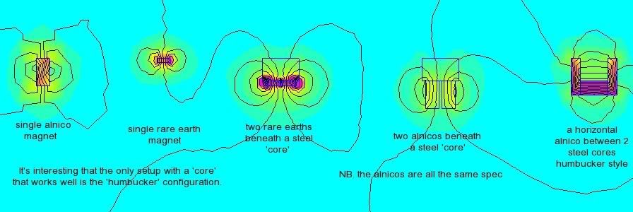
Here's a femm plat that compares various conficurations of rare earth, alnico, with steel core, without steel core.
(This is just the permanent field, but it is very important.)
As was suggested earlier in the thread, you can see how magnets beneath a core don't work very well (unless the core is very short and compact).
This example also provides some insight into why I've had success with a 'humbucker' style layout.
cheers
Col
-
Some interesting new developments!
I had similar ideas. Take thicker wire but keep the old amount of turns. Compensate with an extra resistor. Add a capacitor parallel across the driver coil to create a parallel notch. I don't know the English expression but this should multiply the current times Q at the resonance frequency. Phase shift at resonance frequency is 0 degrees. But at other frequencies it's not
Interestingly, the basic 8ohm 0.2mm single coil driver at 1.2mH combined with a 220u output cap has a (small) resonant peak at almost exactly 300Hz - just where we need drive to be most efficient !
Anyway, I've built a new driver.2 x 90 turns 0.25 wire, 8.5 ohms, 1.8 mH.
There is a bigger gap between the blades than on the previous version, the blades are somewhat thicker and I used an iron bottom plate (instead of plastic on the previous one).
My first impression is that the new driver is a lot more efficient.
Loose plain E string swings a lot more.
Cool
cheers
Col
-
Now that kind of strategy does have some warrant Col...that would be a far more obvious and productive kind of approach. The Hex thing was going to head into that direction, drivers built to optimize drive for a given string rather than driving it with a hex signal...in large part because of the interaction between drivers that occurs regardless of independent signals.
I gather the desire is to get more efficiency? Lower power, cleaner headroom, battery life...that kind of thing?
That's the idea.
There are some potential problems that may or may not be difficult to deal with.
There will be some interaction between the two coils, changing their inductance values a bit through mutual induction. I don't know how to calculate this, so it will be down to building and testing. Unfortunately, I'm not a work-a-holic like you when it comes to building these things
I'm also concerned about the area around 300Hz (open high E string).
It seems like it should be good with both drivers operating at that frequency, and the overall phase shift and impedance at that frequency are ideal, but there may be some phase difference between the two individual drivers. I'm not sure how much, or what effect it might have, so 'fingers crossed'.
Interestingly due to the wonders of phase the current through the main lead will be noticably less than the sum of the two current values through the two drivers - even though they are both fed in parallel by that main lead. I suppose that when there phase difference has cancelled out some of the power, the effective value will be that of the main lead....
Anyhow, its all very interesting. Its a bit like the old idea of having 'woofer' and 'tweeter' drivers, except instead of being optimized to give an even amplitude response over a frequency range, they are optimized to give even impedance and low phase distortion.
BTW, you will love the fact that each coil will be using a different wire gauge - 0.31mm for the big coil and 0.23 for the small.
cheers
Col

Hexaphonic Project
in Electronics Chat
Posted
The physical distance between pickup and driver adds a significant phase shift. The angle of shift is dependent on which fret you are playing at.
It is not difficult to track a monophonic pitch, you can then calculate which fret is in use per string (in a hexophonic system)
To use that info to generate a predictable controllable harmonic would require a fairly complex filter, but you will know which string and which fret is causing the fundamental, so if you can build up data tables of the phase response of your system per string, you should be able to set up a working system.
You would need decent processing power though, and building the filter will be a big job.
Not sure how useful it will be though - totally predictable completely controllable harmonics don't sound like fun to me - the fun of harmonics is exactly in their wild unpredictable nature, and the energy this gives to the sound.
cheers
Col