


col
-
Posts
628 -
Joined
-
Last visited
Content Type
Profiles
News and Information
Tutorials
Product Reviews
Supplier Listings
Articles
Guitar Of The Month
Links and Resources
Forums
Gallery
Downloads
Posts posted by col
-
-
3. Start thinking about having two coils 'rowing together' in parallel
I'm therefore thinking of resurrecting my TDA7053A, if steps 1 & 2 don't work...then feed the TDA7053A the just one mono signal into both strereo channels .....& then out to two separate coils. This ought to put a *lot* more firepower at the business end on demand
I think what zfrittz is suggesting here is that running two coils connected in parallel from the same amp will give you more drive for the same DC resistance and effective inductance - two 2.4 mH (in || = 1.2mH) coils taking half the current each will give you more drive than a single 1.2mH coil
(half the current through 4 times as many coil turns = double the drive, although, in reality, I think the gain will be less due to coil coupling effects etc. I'm not so sure that his suggestion to have the coils as close together as possible is correct)
A big win here, is that the TDA7053A has a more flexible logarithmic DC volume control (vs the TDA7052A) - so rather than mess about with JFETs - which, even though work admirably with my PIC ...they're not linear within their ohmic region (you can linearize them, but then you lose a lot of dynamic range - http://freespace.virgin.net/ljmayes.mal/comp/vcr.htm )...which makes for somewhat fierce fluctuation in gain.It makes sense to try & take advantage of the hard work done by the chip manafacturer!
BTW In a moment of madness/frustration/puzzlement I did at one stage revisit the LM386 last night...it's a truly awful little piece of junk. Bearing in mind there's very little cost difference between it & other poweramp chips...based on what I saw on my scope, I'd urge everyone to avoid it like the plague.
I think the LM386 is very sensitive to the load its driving. Did you use a nice big output cap and a zobel network in your test to keep the impedance it sees at its output more constant?
My MarkII circuit produces clean sustain on all strings, using an LM386. Petes system produces clean sustain using an LM386.
EDIT looking at the datasheet, you can see in the charts that increasing the impedance to 16ohm will increase the distortion levels dramatically, even at lower output levels. A 1.2mH driver is going to present an impedance of over 16ohm for any signal over about 2kHz. Without a zobel or some other way of keeping the output impedance down at around 8ohm for higher frequencies, there will be lots of distortion.
A similar problem occurs if your output cap is too small, but the distortion appears on low frequencies rather than high ones.
As far as action, you are correct, its a big problem. I like to play with a high action and really play hard - it sounds way better - but that is a problem for sustainers. It's always going to be a problem though, no matter how powerful your amp is. The magnetic field drops off with the square of the distance so the difference between 4mm and 5mm is significant.
The ideal sustainer guitar would have a short scale length, no trem, heavy gauge strings, low action and crap pickups (that have no 'character' due to a very poor resonance.)
Don't forget the final purpose is to play the guitar. You don't need or even want exactly the same response on all strings, as long as there is some type of useful response on most parts of the neck, it is a worthwhile addition. Surely no-one wants or needs sustain on the 20th fret of the low E string. Poor sustain on the open high e string is also not really a major issue, just get that note elsewhere if you want it to sustain.
I'm more concerned about how it sounds in the places where it does work, and how it responds to playing.
e.g. does it choke the natural sound? will it kill natural and pinch harmonics? does it produce a lively sound or a boring sinewave? what happens when I play chords? how fast does it respond to different types of playing?
here's an example of the kind of thing that might increase playablility:
using your PIC, what about sensing the strength of the initial attack, then producing a strength of sustain depending on that ?
So if the player plucks gently, the resulting sustain will be a soft low level one, while if they hit the string hard initially, they get a full blooded drive sustain.
This is the kind of thing thats doable with an analog approach, but not practical.
cheers
Col
-
Some thoughts about fizz, squeal, grunge etc.
Guitar pickups are designed to sound good to our ears, not to function well in close proximity to a sustainer driver.
Most guitar pickups sound the way they do partly due to their resonance properties. The resonance is caused by the relationship between the resistance, the inductance and the capacitance of the pickup.
Most guitar pickups have a resonant frequency between 2kHz and 5kHz (Humbuckers closer to 2k single coils closer to 5k)
This next bit is based on intuition, so may be completely bogus, but I'm interested to hear if anyone has any thoughts on this.
Most of us have experienced squealing feedback with our sustianer experiments. I reckon that the squeal is likely to be at the resonant frequency of the pickup.
I also think that the pickup is going to be MUCH more sensitive to EMI at frequencies near its resonant peak. If so, this is bad news for us because those frequencies are not required for good sustainer performance. However, any atonal harmonics and noise caused by clipping or other distortion that fall near this frequency are going to be magnified by the pickup, and will be heard as fizz etc.
I've been thinking about solutions, and the most sensible and likely to succeed IMO at this stage is a passive notch filter placed between the circuit and the driver. Not sure yet what that will do to the phase response - I'll have to go and work it out. A low pass would be simpler, but might not be good enough at rejecting the target frequency.
Edit - changed my mind about the notch filter...
Any ideas about a solution for this ?
Maybe a bandpass in the LM386 feedback, although that might be unstable.
(FWIW, The resonance caused by a driver as used in the designs on this thread combined with a 100u - 220u cap falls just where we would want it. at or near about 300Hz - yet another reason why Pete ended up where he did after his many many iterations)
So any thoughts on this?
cheers
Col
-
Basically, the idea is that once the input is loud enough to register, but is still a low level, you should be giving it maximum drive.
What you describes, sounds to me like a bog standard AGC approach with threshold ...ie cranking the drive when the incoming note is low & vice versa (or am I missing the salient point?!).
You might be missing the point, I'm not sure.
With a 'normal' AGC - e.g. a compressor or a limiter, the gain is reduced for higher input levels (and/or increased for lower input levels).
The difference is really one of scale.
A normal compressor/limiter tries to ensure that the output stays at a similar level over a certain range, or that the dynamic range is reduced - so low level inputs produce output that is still lower than high level inputs just not as much lower...
What I'm suggesting for the sustainer is that the outputs for a high level input signal should be lower than the outputs for a low level input signal - the dynamic range is inverted.
Another way to look at this is that the driver and pickup become part of the feedback loop for a standard compressor limiter - where it is trying to achieve an even output level, but this signal should be even at the pickup rather than some where on the circuit board.
To achieve this, there are two important factors:
You need a powerful amp & driver so that unresponsive strings can get loads of drive. (More responsive strings will quickly have their drive reduced)
You need the response curve of the AGC tweaked so you get just enough sensitivity to low level signals, but at the same time, the threshold where the output drops off rapidly for higher inputs is in the correct place.
If you can get this set up correctly, everything else just works.
You get a sustain with a very even level over most of the fretboard.
There will be some variation - weaker areas will have sustain that takes slightly longer to kick in.
Some parts of the neck will tend to bloom harmonically while others don't...
But generally, this approach to AGC will automatically account for differences in amplitude response due to: action, string gauge, phase difference, pickup frequency response etc.
...but because the action is so high & therefore the string that much further away, what it really needs is for the drive seen at the coil to ramp up *very* quickly, in order to get a 'grip' on that string before it fades past the point of no return.With the AGC set up as I've been describing, as the string fades, the driver output will increase to give as much power as the amp can supply.
If it still can't 'grab' the string, then there's no kind of AGC that will help you. You need either a better power amp. Or, for that particular note on that string, your systems phase response is getting far enough away from optimal that it's not providing a constructive drive.
cheers
Col
-
Anyway...how are others dealing with the seemingly *huge* variation in output requirements to 'excite' those string that are close to the driver & those that are far away? I'm struggling here to rationalise how this will even be possible & *not* have a current hog of a poweramp 'beast on board'.
My Idea of "dynamic range inversion" thought up yonks ago was intended to deal with this problem and it WORKS.
Crap name, but thats what it does (over the desired range) high inputs map to low outputs and low inputs map to high outputs. There is a flat area where maximum output is retained over the first half or so of the desired input amplitude range, then the output ramps down as the input is increased.
The only trouble I have is that its hard using analog components to have enough control over thresholds and slope of response curve. You shouldn't have any trouble with this. I want the size of the flat area of maximum output to be longer.
Basically, the idea is that once the input is loud enough to register, but is still a low level, you should be giving it maximum drive.
As the input level increases, the drive is reduced. At the point where the input is as big as you want it, the drive should be minimal - just enough to keep the string going, but not enough to accelerate it.
This way, the weaker areas of response get more drive for longer, and when they settle, they will be constantly driven harder.
Power efficiency is also improved using this approach. You need much more power to 'swell' a low level string pluck up to full sustain than you do to keep a very responsive note going at your desired sustain level. This approach shoudl supply just the right amount if its set up correctly.
This does work pretty will in evening out the response of various string/fret combos. There is still some variation in response, but not enough to be annoying.
The problem I had was that if I have my markII circuit set up sensitive enough to boost the low levels, its reducing the gain to early on the sustaining string. The sustain is good, and even, but not quite lively enough for me. This is the problem with setting the thresholds using analog components. If I could add another few op-amps, it would be easy, but the parts count is already too high.
PIC wise, probably the way I would go if I were you, rather than using calculations of 'deviation' and decision branches in the code (that seems to be what you were describing?), I would go with a look up table and some linear interpolation. That way its VERY easy to change the response. You could even have different modes by just switching look up tables. You can scale and bias the tables as well. So you just have table lookup with some very simple arithmetic.
Depending on your programming chops, you could write a little app on the PC to create the tables. Or maybe cobble something together using Excel.
cheers
Col
-
I agree that the initial guitar signal is *very* rich in harmonics...but you'd be surprised how quickly these settle, resulting in something more akin to a sine wave.
I'm not talking about the harmonic burst during the attack. I'm talking about how the string vibration changes through the horizontal and vertical axis. The sustainer can only drive the string in the vertical plane.
I reckon (yep pure conjecture, but bourn out by listening and fiddling) that the sooner the sustainer grabs the string and yanks it out of its natural vibration, the more likely that that transition will be noticable/audible. If the sustainer comes in smoothly as the string naturaly settles into more or less a sine wave, then it will sound more natural. It's hars to get this to happen without either a small dip in volume on some string/frets, or a more aggressive 'audible' sustainer sound on other string/frets.
In the end, it doesn't really matter. I was just making the point that the natural physics of the guitar will limit the advantage that fine control over the system gives you with a PIC controlled AGC.
I would still prefer to go with a full digital signal path if I was going down the PIC route. This would allow the fine control your describing over the phase as well as the amplitude. No fet would be required. It may also make it easier to use some of the 'digital' class-d chips out there in order to further reduce the parts count.I don't think that'll be possible with PICs for a good while. the only option then is something akin to a Variax board - take your guitar signal, AtoD it using dedicated AtoD chips, a chunky motorola DSP & do it all in software ....end result? A board that's fairly big - oh, yeah...it'll cost you £200+ to make!
The PICS in this chart have features like
40MIPS cpu, hardware 17bitx17bit multiplication, fast barel shifter, 16k RAM, 16bit architecture, A/D and D/A converters, 128k program memory.
Programming wise, I can certainly do software AGC, filtering and delay/reverb effects with this. probably some sort of multi-band processing although there might not be enough grunt to have enough bands with tight enough crossover between them.
It would be a lot of work though. And not much fun.
cheers
Colin
-
Incidentally, last night was the first chance I've had to try & integrate my 'digital PIC AGC' with my analogue sustainer electronics - as a first run, it went *very* well. I have full control over how quickly the sustainer kicks in after a string has been plucked (ie how quickly the sustainer takes up the slack as the string fades out.... the idea being towards a seamless 'marriage'), what preamp gain level the AGC should start at, how quickly it reacts to incoming signal variation (ie how quickly it adjusts the gain) - both 'initially' (ie to get to the approximate gain 'region' real fast) & then 'final' (a 'finer AGC' takes over ...this is needed to stop AGC 'hunting'/pumping, where the sustain level ramps up/down as it tries to get to the optimum gain setting), ...also it's easy to set the string threshold to cease the sustainer (plus other cool stuff, like 'initial full sustain'...changing to a setable very slow sustainer release/fade out) ...I'm chuffed to bits. The mind boggles as to how the commercial units have got their's working in discreet!
Thats good news.
A couple of things:
There will be a limit on how much control you have at the point where the sustainer takes control of the string. This is caused by the way the natural vibrations of the string change after the pluck - they go through a weird combination of horizontal, vertical, eliptical and figure 8. The sooner the sustainer kicks in, the more damage it will do to the character of the sound.. leave it too long and there will be a dip in output. It's possible to get a good balance, but you won't have a lot of leeway there, unless you're going for a quite synthetic sustain sound.
As far as how the commercial units have got it all to work. Its not an particularly difficult project as long as you can use big boards and/or smd components. There are ways to control the various features of the system without resorting to software. Having said that, software is a nice way to reduce the parts count.
e.g. theres a nice little circuit snippet in one of the THAT corp app notes that shows a 'non-linear capacitor' (I think thats what they call it). It uses an op amp and a few discretes to create a simulated cap that allows a very fast reaction to an initial signal, then a much slower reaction after the signal has begun. This does what you discribe - preventing pumping and distortion due to the attack time being set too low.
Of course, these extras cost money, board space and a little power.
I would still prefer to go with a full digital signal path if I was going down the PIC route. This would allow the fine control your describing over the phase as well as the amplitude. No fet would be required. It may also make it easier to use some of the 'digital' class-d chips out there in order to further reduce the parts count.
I could experiment with delay/reverb effects to better mimic the 'loud guitar in a room' type of feedback. If the chip is powerfull enough, multiband control so phase and amplitude could be tweaked depending on frequency. Hehe, with enough processing grunt, you could have lots of fun.
I still want to get the basic analog version set up as good as I think it can be.
I've been playing around with lenearising resistors around the fet. These do reduce the distortion , but they also increase the response time somewhat.
So I have some experiments to do on the breadboard as soon as I have time.
I also really need a scope

cheers
Col
-
ok, so at 3mm long, it's small, but this isn't insurmountable
Pretty damn tricky though. How would you do this? Dead bug style ?
Maybe not so bad if you have cnc, or all the kit for etching your own pcbs.
Any suggestions for the rest of us?
-
From what I understood from the article the power consumption has to do with the real dead time setting and switching frequency. I wouldn't be surprised if the voltage was the determinant factor, but that's not what the article says. Only one way to find out. Swap capacitor and see what happens.
I suppose that most of the losses occur during the crossover.. caused by dead time, linear mode operation.. whatever... (my class-d knowledge is minimal)
If you reduce the carrier frequency, there are fewer crossovers, so efficiency should be improve.
If you reduce the carrier frequency, in order to avoid an increase in switching noise, the low pass filters cutoff needs to be lowered, or the Q increased or both.
I think this would be a good option for us though. For normal audio, you would want a good response up to at least 18kHz, for our sustainer we probably only need to get to 1.5kHz - 2kHz max, so plenty of scope for reducing the carrier frequency.
cheers
Col
-
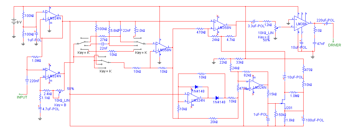
Here's the feedback version showing 82Hz a 450mV input.
The clipping in the first wave cycle dempnstrates that the AGC only takes 2-3 cycles to kill the peak and settle to a steady output. You can see in the last couple of cycles that there is some distortion (look at the shape of the -ve peaks). This only happens at very low frequencies, and it more prominent at higher input levels.
(off the page to the is a unity gain buffer and to the right is an LM386 power stage)
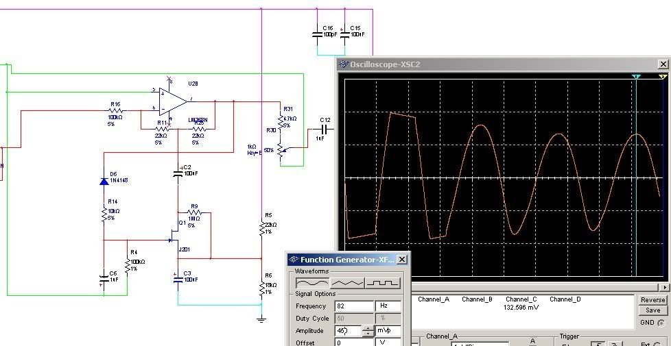
The light blue is ground, the green is virtual ground (4.5v)
Note the divider(22k & 18k) that sets the voltage at which the jfet starts to become sensitive to the control voltage, this allows the circuit to fully use the linear part of the jfets resistive range (I think ?)
The 10k and 100k resistors under the diode control attack and decay (according to the 'fast peak limiter' article, the large one should be at least 10x the size of the small one).
I suppose that with a scope, you could use a trimmer and really squeeze the max out of whichever actual jfet you use in a real life circuit.
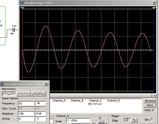
Heres the same with 150mV input, you can see that there is virtually no distortion.
Now with 650mV to show how the distortion at higher input levels manifests itself
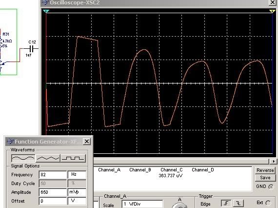
The feedforward design is more elegant IMO because by the time higher inputs are causing distortion, the output levels are much lower, so the distortion is barely audible.
With the feedback version, the difficulty will be to set it up so that it is sensitive enough to low levels, but at the same time, full sustain input levels are still low enough not to cause unacceptable distortion.
Increasing that window is doable, but requires the addition of extra components.
eg. a dual op-amp with one half improving the diode rectifier - no other extras there, and, for the feedforward version, the other half of the op-amp providing separate control over the gain to the control voltage (no extras there either as you can then use a follower for the input instead of a gain stage).
cheers
Col
-
Sorry for the English translator of google.
If you can not find for Simulation lm386 nothing happens, I see how it simulates.
If you look good in the waveform above the circuit has no deformation in the wave, but with only FETS, there is a cut of the wave, that is the distortion at low frequencies is larger and if you can hear , because a FET is a distortion, but if we use a transistor as a regulator and OP as a wave attenuator is not cut.
Saludos
That transistor regulator is very interesting.
Having said all that, I have a simple circuit with (excluding input and power buffers) uses 1 op-amp, 1 jfet, 1 diode and some caps and resistors.
In feedforward config, it has very little distortion up to the point where the input gain amp clips. At which time, the peak output is only about 15 % of the output with normal sustained string level inputs. There is also an increase in distortion (not clipping though) at very low frequencies that is slightly worse at higher input levels.
In feedback config, it can achieve low distortion and a reasonably level output amplitude with inputs from about 150mV to about 450mV
below 150mA, the output reduces gradually, and above, the distortion increases, soft clipping the tops of the wave.
The distortion at 82Hz is a *little* worse, but nothing like in zfrittz pics. The attack and release both take about 2.5 wave cycles at 82Hz (so very quick)
I favour the feed-forward version, but as with any simple circuit (and with the feedback version), the difficulty is in setting the thing up to work with a particular driver, pickup and guitar. There are going to be short burst of slightly audible distortion as the string decays to the point where the pickup doesn't output enough to drive the AGC into distortion, but these can be minimised by carefully tweaking all the settings.
I am definately going to investigate Zfrittzs circuit with the extra 'regulator' transistor though - that might give even output over a broader input range and even lower distortion levels.
cheers
Col
-
I saw the following schematic in the Dutch Elektor may 2009 (Power in the pocket - eenvoudige PWM-versterker by Ton Giesberts)
Is not included in the english release of may, it might well appear a month later.
Self-oscillating PWM amp
1W / 8 Ohm, 1.7W / 4 Ohm
Power supply: 6...9 Volt
cool
A modification to reduce the power consumption at rest would make the amp more suited for the sustainer.So how would you go about that ?
cheers
Col
-
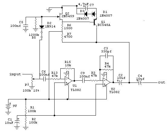
Interesting schematic. What does the Q1, D1, D3 network do? Is it some kind of error correction to reduce AGC distortion? or something much more mundane? will have to investigate further.
===========================
I've had some success with a vastly simplified version of my own circuit that I've been working on over the last few days.
Rather than apply a bias to the dc control voltage, I've used a divider to bias the jfets working 'position'. This meant I could scrap the op-amps and use a simple 1 diode half wave rectifier, but still get the tailored response. I got it up and running on the breadboard tonight and it is extremely promising.
Still work to do, there is some noise at lower frequencies, and the overall noise levels are not as good as my old system. However that was fully soldered up and installed, rather then a big mess on a bread board. I have also to add a zobel network to the power amp to reduce the load in the higher frequencies where my mixed mode amp (intentionally) tails off - this should help to tame the LM386.
cheers
Col
-
@psw & col
I want to share with you the schematic of the mosfet compressor I have.
I've found this one on the diystompbox forum some time ago. Could it be that this one is the original and that the ones that zfrittz6 and psw have posted are derivatives?
Yes you are absolutely correct. The version Pete posted is one of the successors to that one, the designer Brett was also involved in the Aussiemart thread, but changed the name of the circuit after he included ideas posted by others into the design.
I'm not sure about the one zfrittz posted, but my guess is it's taken from one of those and re-drawn, he may have lost the original pic. I would imagine that he wasn't trying to 'steal' or 'take credit', rather he was just posting these things as a way to bring them back into the discussion for those that missed them when they firs showed up.
You might be right about the output cap, I don't remember the details, however, I still don't think this circuit could provide the kind of low distortion level we're after for this project - there will be a lot of asymetry. Probably good fun as a stomp box though.
cheers
Col
-
*Lots of ideas about using a PIC for AGC*
So, rather than using the pic solely for AGC, can you:
A/D convert the raw input signal
apply software AGC (plus harmonic modes etc)
use the output PWM as part of a poor mans class-d amp ?
So basically the input goes (through a buffer if required) straight into the PIC. Then from the PIC output, straight into a mosfet push-pull switching output stage followed by driver plus any filtering required?
I know the devil will be in the detail, but is this feasible?
If so, it could mean an efficient, compact driver circuit.
How much current does the PIC use ?
what frequency does the PWM run at ?
what are the part numbers for the actual devices you are using, so I can check out the datasheets?
As an aside, processing the main signal with the pic rather than just the DC control voltage should make experimenting with phase for harmonic modes much easier. It really depends on how much grunt the PIC has though.
We can work at a relatively low frequency, and shouldn't have to worry too much about aliasing distortion, but the more processing required, the more powerfull the chip has to be.
With some of the more high tech PICs, you have multiple ins and outs. You can also get ICs with multiple matched pairs of Mosfets that can handle ~300mA which would be plenty in a hex system.
cheers
Col
-
FWIW, I think that the approach Pete has described of using a switch to shut off the power and turn it on in bursts is worthy of some development energy. I would approach it afresh, with a different circuit topology... I guess building in some varaible hysteresis rather than(or as well as) using a decay time might help a lot. Worth some thought for sure.
It seems like a good way to improve efficiency.
I'm not sure I'm following the line of thought - do you mean power efficiency?
yes, power efficiency. if the sustainer can be off for some of the time while it is functioning, then there will be some saving. Not as much as a class-d.
Maybe my instinct is wrong (haven't done the sums), but I would guess that repeated equal bursts of full power then nothing would be more efficient than steady half (output) power when using a class a/b amp?
Unfortunately, there is another issue with the class-P burst mode amp - low level inputs will still be low level, it doesn't equalise the levels as much as a good AGC would. I suppose that you could use lots of gain, but I would imagine that this would give you clipping in the on bursts, and the off bursts might be long enough to make the on bursts noticable... just guessing. Anyway, tfor it to work as I would want, I would want to combine it with a standard AGC to get the low levels up without clipping the high levels, so it becomes kind of redundant, also for it to work well I think some sort of shmitt trigger would be needed to provide hysteresis in order to prevent jittering around the on/off point. this requires even more circuitry.
If so, it has merit - & it's is one of the (offshoot) benefits of using a PIC ...ie you can program it to say for example "when the input signal level drops below X volts, then make the output pin low"...this then feeds the Power Amp chip DC volume control pinYes, that is certainly an advantage, you can experiment in software
What I don't fully understand is why you need a pic to provide what can be got from a dual op-amp set up as a precision full wave rectifier ?
Thanks for your schematic...that's actually a very good circuit, though there's perhaps a bit too much component count going on there! Is this soley your design or is it a tangent off a group effort some few hundred pages ago?! What's your honest appraisal of where you're at with your Sustainer? (in other words, what does your design do well, & what still needs refining)It's my design. Based as I've stated on two of those articles I posted links to. I then used a full wave rectifier with a dc bias (feeds into the second op-amp in the rectifier) to provide a DC control from the input. So I didn't create it from scratch, but I found the sources, pulled them together and wrestled it into shape.
As far as performance, it does most of what it was intended to. Distortion levels are low enough so that there is no fizz, and only a little low frequency distortion heard occasionally on very low notes (compromising response time vs distortion).
The response times from the real circuit were not as good as I had been hoping based on simulations, and I couldn't understand this. I was also not completely happy about the maximum drive - it produces a good clear sustain, but not as lively as is possible.
The harmonic modes work, and there is some variety, but after the initial fun wore of I got a bit bored with them.
My initial intentions were to create something that allowed the natural sound of the guitar through, and I felt that this system was a little sterile. Although a vast improvement on the basic non AGC versions.
Since designing that circuit, I have discovered an embarrassing error in my calculations/measurements that explain (I hope) the not so stunning response times.
I measured the voltage level of the pickup output when sustain was strong at around 150mV. So I set up the circuit to start pulling back at around this point. I've recently discovered that 150mA as measured by my DMM equates to around 220mV as a setting on the virtual sig-gen in the simulator! I messed up some where between peak-to-peak and RMS.
Aside from that, recently a better understanding of the more subtle details of how it all works has allowed me to make a few little changes that have improved the performance. I've also decided to go a completely different route with the harmonic modes (some experiment that's not been tested yet)
You're right about the component count, but every time I've tried to reduce it, it's had a really drastic effect on the functionality.
In truth, its pretty honed down for what it does (apart from the harmonic modes, which are compact for the number of modes, but don't all deliver value for money IMO).
Input buffer => 1 op-amp
virtual ground buffer => 1 op-amp
Harmonic modes => 1 op-amp
Precision full wave rectifier with built in DC bias. => 2 op-amps and some extras
Jfet based VCA => 1 op-amp (and lots of supporting circuitry)
Power stage.
Thats all
there is to it.It can be compacted reasonably onto veroboard
most of the samples here were recorded using it (combined with a broken amp sim - thats where the occasional clicks and pops come from)
(the clip at the top is nothing to do with sustainers, the one at the bottom was made using the LM13700 based circuit, the rest using the jfet based circuit)
I'm back at work now though, so much less time to play with this, I'll get the new version built and tested asap an post the results.
cheers
Col
-
Col - I see your schematic uses a transconductance opamp....which is a pretty new area for me (I'm aware they yield a current output directly linked to the voltage input)...care to say why you went the transconductance route & what the win is wrt sustaining devices?
Yeah, that was my very first attempt at an agc. It worked, but there were many problems so I went back to the drawing board. My second circuit was very different, and much more successful heres a link to one revision of it - to save you the searching.
FWIW, I think that the approach Pete has described of using a switch to shut off the power and turn it on in bursts is worthy of some development energy. I would approach it afresh, with a different circuit topology... I guess building in some varaible hysteresis rather than(or as well as) using a decay time might help a lot. Worth some thought for sure.
It seems like a good way to improve efficiency.
Curtisas circuit is a good design. I tried to get it to work but failed - although I'm not sure how I failed. Must have been some silly mistake or other. Anyhow, that circuit was his reaction to one of those three articles I linked for you a few posts back.
cheers
Col
-
Here is one description from the designer(s)...How it works:
With small signal input, the mosfet is "off", and all of the signal goes to the op-amp, which puts out maybe 1 or 2 volts.
With a large input signal, some of the output gets to about +3V, and a bit less gets past the diode and charges the cap. If the cap and gate get to 2.5 V, the mosfet conducts some signal to ground and lowers the output. No matter how large the input signal, the output never gets above +/- 3V.
What he is describing is exactly how all thes fet based compressors work, and how mine works, the fet is set up as a VARIABLE RESISTOR not as a switch !!!!!!!!
This is the simple fact that you seem to be unable to accept.
You may be using the fet in a different way, but if you are then your circuit works in a fundamentally different way, and it is not fair to base an argument of the former on experience of the latter.
....but from me after watching that thread and others and doing some work of my own...
g'DAY...Have been experimenting with variations on this circuit for the sustainer application...won't work as is, but certainly got me thinking in new ways about the problem and getting some headway...so thanks for all those contributing to this very interesting thread...
Anyway...I think Brett mentioned it somewhere, this and compressors in general seem to be sensitive to power supply....given the higher gains I am using this is probably a lot worse (I use the LM386 as a Power Amp to driver a load with the sustainer), this seems to be particularly apparent.
Are there any really simple (ie small) ways of stabilising the supply so that fluctuations in voltage or current do not effect function...from a 9 volt battery...that doesn't draw much of that power away or further drain it? I don't want to loose power in the process if possible or shorten battery life!
Otherwise...have been inspired and helped by this to understand J and M FETS much better and transistors in general. Till now I have avoided discrete components favouring opamps for their lego like simplicity of constructing amp stages...also tricky to get some types. Speaking of which...is there a good site that gives substitutions?
Any advice welcome... pete
I read this and it has nothing at all to do with using the fet as a switch, or anything else. Stabilizing the power supply is not too difficult, but requires extra components. It was explained in that thread how you could do it, and I have explained here how I do it more than once.
Stabilizing the voltage feed to the fet is a different thing entirely, but for that, one option would be to do as I did in my design and use a full wave precision rectifier rather than a single diode.
These questions you ask don't 'hint' or 'imply' anything much about different directions you might have been thinking about, or changes in approach to circuit functionality.
There was no SECRET about the directions I was considering, I was working from the site from people who designed and developed the thing and do have the expertise and scopes that I lack...no point posting or asking here now is there.I was talking about principles, not the minutia of particular values of components and directing to the known source of such uses of the LM386 (not me) because it should have been credited and put into context and wasn't. If I have or had made use of similar principles with different values and diodes, it is still the same principle and not what I would regard as a "clipping circuit" nor that of people far more knowledgable than I in that regard...have the debate with them if you seek such a conflict. Personally, the principle will achieve a compression effect, not a distortion (fuzz box clipper) effect and I have proven this to be so in practice. If that is not of interest to you, fair enough...probably wasn't then, maybe still not now.
Your self quote doesn't talk about minutia of components or about principles, is just asks about stabilizing the power supply - which would be a reasonable thing to consider for just about any electronic circuit - certainly not an innovation of any kind.
As far as clipping - your at the old straw man again.
I have not once said that the aussiemart is a clipping circuit. What I said was that it is little better than a clipping circuit. When used as intended, it imparts a lot of distortion to the waveform.So whether you regard you circuit as a clipping circuit it irrelevant - yet another red herring in your argument.
...Well...I'll cut my pointless reply short I think...there was more explanation, however, clearly you are the better man Col, I should have credited you more with all that I have done here.
OK, if you want it that way, fine by me!!
Typical of you these days, Pete, condescending, sarcastic, pig headed.
No-one is trying to take credit for any of your ideas, or for the work yuo have put in. However, I do get pretty sick of the way you prattle on about stuff you don't fully understand, filling your arguments with haze and ambiguity. You get things wrong A LOT, I used to ignore it because you had a bit more respect for others, but its getting silly now. The way you've been attacking newcomers who make the faintest suggestion that some of the things you say might not be correct.
Particularly how you attack people who want to use more sensible engineering methods and scientific process rather than spending hundreds of hours guessing and using trial and error to come up with something that works, but that they don't understand.
It's sad, but if I pulled you up an all the errors and mis-information you have posted here over the years, the page count would be in the thousands.
Your simulations trump my reality and I can't go back 3 years over old ground with any reliability and clearly explain everything. Obviously if I were to "reveal" the circuitry I presently use, I would only be subjected to more abuse. Obviously the same is felt about any questions I have regarding others work too. Perhaps drivers that run as clear as a whistle yet still squeal exist and perhaps an AGC will correct that, I can't comment on that because of what I am not privy too either.Oh dear, more sad attacks on the work of others, based mostly on ignorance. You used to want to help folk Pete. It seems that now you want to stop them in case they succeed without giving you full credit.
None of that actually helps the average person who comes along with simple questions to get a simple device operational or who are looking for simple solutions within the scope of the average DIYer here. Obviously they are of little significance to the grand plans afoot.No, none of this helps anyone at all, but I'm not going to sit around and let you throw your weight around without saying anything.
If you stop attacking folks unfairly, and you might find the atmosphere around here gets a lot more pleasant pretty quickly.
cheers
Col
-
I think you will find that it is not distorting the signal into or out of the LM386...nor does it effect the guitars signal (what I mean by it not being in the signal chain).
It obviously effects the guitars signal or it couldn't alter the volume of it.
Basically, the signal in to the sustainer circuit is cut for a period of time set by the cap effectively and at a point set by the zener diode threshold...The circuit schematic you posted a diagram of in response to zfrittz post has NO zener diode.
There is no "fuzz box" hard signal clipping at all, the diode is just there to set the trigger to cut the input, the output signal does not go through it.The signal doesn't have to go through the diode for the diode to cause distortion - the signal doesn't go through the diode in a diode clipper either.
My circuit has a...Ah, so your response to my post discussing the aussiemart circuit wasn't about the aussiemart circuit, but about a different circuit.
The aussiemart circuit is supposed to be a compressor, and does work as a crude compressor in exactly the way I described.
But you proceded to argue that I was wrong, but are basing this on a completely different circuit that you have 'bent' out of one of the aussiemart ones...
We cannot have a constructive discussion about how your circuit works because it is SECRET. Any analysis I have made has been based on the public aussiemart circuits.
Basically the diode will only trigger if a voltage at the output exceeds a certain amount...at that point, the threshold set buy a resistor (perhaps softened by a cap) will send a control signal to the fet shutting off the input...at that point it is off and wont come on till the cap discharges (setting the time and saving power too)...the momentum of the string carries through and you don't here the circuit shutting off with this application.We have discussed the merits of this approach more than once before in the thread, I understand the concept. This is not how the aussiemart circuit you posted is intended to function.
#4 If you don't see where the distortion comes from then you're not even beginning to understand how this 'pretty simple' circuit works(or doesn't).I beg to differ of course...look again the diode is the trigger and not in the signal path except to trigger the fet off, cutting off the input to prevent overloading the input and distorting (depending on the amp and the thresholds of course).
Differ all you want, you are wrong - the diode in the aussiemart circuit is not a 'trigger' it is intended to function as a half wave rectifier.
It may be doing something different in your circuit, but that is irrelevant unless you're going to publish it.
#5 something that is triggered asymmetrically and cuts gain completely is little better than a diode clipper. Which is exactly the results I described in my previous post. A diode clipper* would at least offer symetrical clipping, and would have a lower parts count.Nope...no clipping, completely different application...the fet also acts as the buffer and neither the aussiemart nor the spanish version is what I am doing...but pretty much a similar principle. This saves many components that a preamp would normally require if only to prevent loading.
Ah, so you're admitting it now that you're refuting my analysis of the circuit you posted by referring to a different circuit that works in a different way - at least we've cleared that up.
Col
-
Well...I built several variants on the simple aussiemart comp (not just simulations)...the thread there was a development thread with people chipping in to develop a relevant use of the LM386 for this project.
Once you get a feel for the circuit and hear it, it is relatively easy to tweak by ear and response without a "scope"...we are talking pretty simple circuits here. Connect a speaker in place of the driver and you will hear the AGC clamp down on the signal, we really are just talking about a simple switch are we not, none of the AGC stuff hanging off there is in the signal chain, the output and zener are simply a trigger, the rest just determines threshold and release times of the switch...I don't see where additional distortion comes into it other than the LM386...but then it need not be an LM386 and any triggering discrete would achieve much the same result.
Yes, the zener senses asymmetrically from the output and at high gains, the components need to be changed to deal with that...but once triggered the jfet or mosfet of choice simply acts as a switch. So, attaching a speaker you can hear that once a certain threshold is reached, the switch turns the input to the lm386 off (it also doubles to avoid loading issues without an additional preamp stage). The same principle could be done within a preamp stage with an opamp, but the economy of this simple design was certainly attractive to my approach. The time of release is set by the caps.
It can be set to be quite a hard limiting device with very long release times...to none at all. But it is only triggered asymmetrically, it cuts gain completely. Such an action may be just wrong for general compression duties and require finessing as a stomp box, but in our application such hard limiting may well be found to be useful.
I've emboldened some parts of your reply for clarity. I'm now going to be really blunt because I don't want my point to get lost in the detail. and its late.
#1 small parts count does always equate to simple.
#2 The whole reason for AGC is because a 'simple switch' is not enough. (if it was, we'd use a simple switch right?)
#3 if the 'AGC stuff' is not in the signal chain, then it is completely redundant. It must be in the signal chain to alter the amplitude of the signal.
#4 If you don't see where the distortion comes from then you're not even beginning to understand how this 'pretty simple' circuit works(or doesn't).
#5 something that is triggered asymmetrically and cuts gain completely is little better than a diode clipper. Which is exactly the results I described in my previous post. A diode clipper* would at least offer symetrical clipping, and would have a lower parts count.
If you have a version of this in your sustainer and it doesn't add fizz or distortion to the signal, then it is not 'kicking in' while you are playing... which would explain the steadily rising volume of the sustain that you described recently - that definitely would not be happening with a crude hard limiting device like this applied to the signal).
*I'm not advising anyone to use a diode clipper as a limiter in their sustainer - any kind of hard clipping, symetrical or otherwise will add unacceptable distortion to the output of your guitar - assuming it is set up to kick in at signal voltages.
cheers
Col
-
Exactly - as an aside, just about all decent AGC Circuits I've seen require a dual rail approach
Although its often a trivial job to set them up to work with a single rail and a virtual ground - that's what I've done.
That's a good point, but with my intended route, the reaction time (in this instance the JFET's controlling DC level)Ah, of course, I was forgetting that you are intending to use this in combination with a PIC, so its a DC level that you want to vary.
What I did notice last night is that when increasing the power amp gain level (manually), there's a critical point where the whole circuit 'bites' & it starts exciting the string well, but that *very* rapidly runs away & turns into squeal....the conclusion here being is that any AGC will need to be somewhat 'clever' & lightning quick to get to that point of 'bite' but back off quick enough so that the squeal doesn't kick in. In my opinion, that's a tall order for the DIY discreet component route (though it's obviously do-able as there are already commercial solutions out in the market). I also have a hunch, that the driver can be 'right' next to the other pickups, *if* you can control that AGC well (& darned quick)...I reckon the squeal isn't so much a by product of EMI (though obviously it is changing magnetic flux ffields that are the conduit), but more a by-product of unecessary power being applied to the driver (& across all strings) resulting v quickly in uncontrolled positive feedback...in short, I reckon if you nail the AGC (ideally with a smaller drivers ...eg three string, two string or one string variants)), you nail the problem of squeal, which leaves you with a lot more options with respect to driver placement.Unless you're trying to get really close to the pickup, you should be getting fret rattling sustain well before you get into squeal territory.
As far as needing a clever AGC, as long as you use a feed-forward topology, you should be able to set it up to ease off the drive as the input gets to 'strong sustain' levels a little bit of fun with the PIC should achieve this with no trouble.
btw, I can't open the snazzy last cct, as I'm just getting spammed with adverts, & it doesn't take me past them - even when I click on the "Take me to, blah blah")), or at the very least most need a 9V rail (in order to get enough headroom to get into a JFET's pinchoff area).hmm, Heres a link to the diagram - maybe that will work?
cheers
Col
-
For the sake of a bit of balance here (why so rude?), zfrittz6's last schematic, whilst *very* similar, does have quite a few different value components (and some extra ones)
I read that aussiemart compressor thread from beginning to end - what a mess (about 5 different permutations, errors on the schematics etc). I'm not sure anyone got the thing working 'as expected' & looks like it eventually fell by the wayside. Who's to say that the aussiemart OP (Brett) didn't just see a similar circuit somewhere else himself & then post it up with a couple of his own mods? (my point being, in this internet age where things get posted, cross posted, modifed, rejigged, re-shared, remodified etc....it's easy to see how replication can pop up)
Also some aspects of the aussiemart compessor were at best vague (MOSFET variant), whereas zfrittz6's has the MOSFET shown - maybe zfrittz6 nailed the design? I would have liked to have seen some supporting text from him, but hey, he's Spanish & if I was posting on a Spanish forum, I wouldn't have posted up much in the way of accompanying text in either!
Agreed.
Although, I've set up simulations of the various versions of the aussie mart, and of zfrittz's version, and none of them do anything like a suitable AGC for this project.
Of all of them, only one of the ones in the aussiemart thread works at all, and it is little better than an asymetrical clipper.
You have to remember there aren't *that* many ways to control an Opamp's level (automatically) & most decent variants use either a MOSFET OF JFET either in the feedback loop or at the opamp input (as it goes, here's one I've just found that looks promising as it works off just 5V...which is exactly the VCC level of my present line of attack -Yes, jfet or vactrol seems to be the way... apart from stuff like VCAs and LM13700 type circuits.
That circuit diagram you posted is a very simple basic afair - the only thing thats not bog standard seems to be that the fet is attached to the positive rail rather than to ground.
There are a number of problems with that type of circuit. Particularly the reaction times can be higher than we would like, and distortion at low frequencies can also be bad.
Here are links to the three best circuits I've found for using a jfet as a basis for AGC.
a simple 'fet attached to feedback loop' design
a very nice 'carefully biased fet attached at input to op-amp'
a snazzy but tricky twin fet circuit that keeps the fets in their linear region. (click on the print friendly one to get a version with the diagram and text together)
I really like that third one, but I'm worried about the trouble I (and others) will have matching and selecting devices and then tweaking the result without a scope.
I've been back working on my old circuit, updating it a little. I've spent a lot of time recently on various other attempts, but the original is still best by some margin.
It is a combination of the first two of those three designs.
It uses the clever jfet biasing from the first article 'fast peak limiter', but uses it in the feedback loop of an op-amp similarly to the that second article. In addition, rather than taking the control voltage from the output of the op-amp, I'm using the circuit input, rectified and scaled as a control voltage.
I've been able to increase the size of the band between threshold and limit compared with my earlier design, and make some improvement to the reaction speeds of the circuit. I'll be testing soon. Hopefully I'll have some good news.
It will output a fairly even output level for inputs between about 70mV peak to peak and about 220mV peak to peak. above and below those, the output level drops. The input has a gain control so the circuit can be adjusted to control this range. This allows it to work with different pickups, although if you increase the low level sensitivity, the upper limit is reduced.
You can find earlier versions with basically the same approach posted in the thread.
While I'm here, here's my first handwound 6 string driver (literally! ie holding in one hand & winding with the other - no jigs, vices etc). I used 0.15mm wire ....the core metal is about 1mm thick "L" shaped - taken & cut up from a general metal scrapbox (I think this metal was originally something to do with a PC's PCI bracket - anyway, it's ferrous!) just potted it with paraffin wax- it'll have it's first trial run tonightGood to see you're having a bash at the 'standard' design - albeit your own variation.
...Heh, I've found that the best stuff fo a core is the plate they use to make the chassis for pc power supplies. It is very magnetic (as you would expect - it needs to provide shielding). Its thin so good for laminations, and it's soft enough to cut up with a pair of tin snips.
My single string drivers (0.1mm wire) are sustaining the strings well (including top 'E' & 'B' strings, just honing the supporting AGC circuitry...last night I was investigating whether the AGC works best applied at the power amp chip or the preamp chip. With the poweramp chip I'm using (A TDA7052A), AGC worked best there, but I really want to get the AGC working better at the preamp stage as that's where I'd prefer it went (better interfacing with with for example Roland GK pickup boards etc)I've also wondered and messed about with applying the AGC to the power amp, but so far not fount it to be as easy, as 'good' or as practical.
I got it to kind of work with the LM386, but it was no where near as good as the pre-amp versions I've hacked together.
Might be good with a vactrol though... and that might also provide a super minimal circuit. The problem with the jfets is that the range of resistance that they can provide linearly is too puny to be useful with the LM386. Vactrol might work in this respect.
I like the idea of keeping the power stage and the rest of the circuit separate - this should make it easier to swap out different power circuits to test.
enough for now
cheers
Col
-
sorry for changing a bit the discussion..but, about the driver, the copper wire has to be "enameled", or can be used also common 0,2 wire like this: http://www.banzaieffects.com/Copper-wire-0...27372.html#tabs ?
The wire must have insulation.
So basically, the only suitable wire that's readily available is 'enameled' wire.
cheers
Col
-
would anyone help me to wire the driver, amp and my JEM555, which is H/S/H ??
coz i hv no idea of those colorful wires...
sorry that i live in HK, so it is a bit difficult for me to read through all pages from the beginning to 307...
the only thing i don't understand yet is the circuit of my guitar... (bcoz u guys are mainly using the strat... )
thx a lot!!
First of all, have you built and tested your circuit and driver ? if not, then do that (a few times probably) before even thinking about installing into a nice axe.
Secondly, AFAIK, no-one has successfully installed a sustainer based on the designs here on a H/S/H guitar. There are a number of potentially significant hurdles to overcome.
I suggest that folks swap out the neck humbucker for the driver and live with not having a neck pickup. Or better still, get a cheapo second guitar to do sustainer experiments with - at least until you have it all working perfectly with other pickups etc before tearing apart a beloved favorite guitar.
cheers
Col
-
Please don't be discouraged. I appreciate what you're doing. Though it's slightly over my head I read regularly and enthusiastically. I look forward to reading more of your results with this new circuit and seeing a preliminary dwg when you're ready. I've been keeping quiet here (as I am sure many others are as well) as I "learn" some more basics and tinker.
Thanks.
I'm not too discouraged - still working away here
More stuff in development at the moment, it shouldn't be too long before there's something worth posting to the group.
My new driver works, but the LM386 is not the right output stage. Not because its noisy, although that doesn't help. It's because it can't drive a 2.5ohm load efficiently so the benefits of reducing the DC resistance are wiped out.
As a result, I'm busy learning how to 'design' a discrete push-pull output stage.
Its going well at this point.
I am concerned that when it comes to building and testing, I'll have problems with thermal runaway and other issues that are hard to solve without experience and suitable equipment. You never know though - it might all just work... lol
My super simple AGC worked, but not well enough, so I've hacked together another one which is still un-tested.
Plenty to do before its time to go public.
cheers
Col

Sustainer Ideas
in Electronics Chat
Posted
-40 to +20dB in 31 discrete steps ? it this going to be enough control granularity? yeah, probably.
But you're right about the size putting me off - and many others I would guess.
I would also like to get a more powerful output stage, however, I really want to avoid SMDs.
A class-d output stage might convince me, but it would also mean going back to the drawing board on the AGC.
A THAT corp based AGC with a nice filterless class-d on the output could be really nice (and expensive)
Anyhow, I'm looking forward to hearing how you get on with the new IC, so good luck with that.
cheers
Col