


KeithHowell
-
Posts
525 -
Joined
-
Last visited
Content Type
Profiles
News and Information
Tutorials
Product Reviews
Supplier Listings
Articles
Guitar Of The Month
Links and Resources
Forums
Gallery
Downloads
Posts posted by KeithHowell
-
-
There has been some interest in changing the templates into CAD format so I decided to document my process here:
1) Go to the WinTopo website and download WinTopo Freeware WinTopo Freeware
While pdf's to be converted
2) Open the PDF document and select everything using the Tools->Select&Zoom->Snapshot Menu Option
3) Open a copy of Paint and Paste the image into it and save the file as a bitmap (.bmp) file.
4) Open your copy of WinTopo and load the just saved .bmp file (File->Open Image)
5) Go to Vector->One-Touch Vectorisation and vectorise the image. (Vector->Set one-touch options allows you to play with the settings to do this but I have found the defaults work fine for such a clean image)
6)Save the vector drawing as a DXF file. (File->Save Vector as)
7) Open the DXF file with your CAD program and Scale the drawing size using the 1 inch by 1 inch block. If you want it in metric set your measurement system into metric and use the then 25.4mm by 25.4 millimetre block to scale it.
More Files? Go to While( step 2) else end
Unfortunately the PDF file contains an image for the actual template so this method is necessary. Other PDF files like those on the Fender site Fender Drawings Contain vector drawings and can be converted directly to CAD via the DXF format by using GhostGum GSView
I also see the newer version of WinTopo will allow loading of other format images like .jpg and .tif The older version I have installed only allowed .BMP so in step 4 above you can choose a more compact format.
Keith
-
After a bit of fiddling I worked out how to convert them to CAD format which I find more useful.
If anyone wants in CAD format let me know.
Keith
-
-
Electricity is weird stuff
Yip but it is all very logical. I think the most important thing is correct grounding! I can tell you quite a few stories about bad grounds on electronic equipment. One case had a few hundred thousand dollars worth of telecommunications equipment destroyed due to a bad earth!
I'm pretty sure you have a earthing problem of your stereo receiver. When I mentioned earlier that the crackles and pops were due to incorrect grounding it was actually the turntable on my stereo setup (this was over thirty years ago) that was not properly grounded.
I also agree: get an electrician to check out your house power supply, corrosion is not good!
Good luck
Keith
-
Tried that, best I could anyway.
Dug up the top of the ground spike, brought out an extension cord, and tested the resistance between the spike and the ground prong of the cord- zero
Yes that may be zero but what is the resistance to ground from the spike? Just because it's hammered into the ground doesn't mean it's a good earth!
You need to check that with a proper earth tester. We always referred to them as "Megas" made by the AVO company which made the AVO (Amps, Volts, Ohms) meters.
This involves hammering a spike into the ground some distance away from the earth spike and connecting the meter between them. You will then be able to get a decent reading of the quality of the earth connection.
Keith
-
I would suggest you get your earthing of your electrical supply at your home checked.
I have had a similar problem on a Hi-Fi amplifier which wasn't earthed properly. All sorts of snap, crackles and pops! Earthing it removed the crackling completely. There was a static build up which when it got large enough to overcome the resistance to earth would discharge and cause the crackling.
Keith
-
I'm not convinced that quarter sawn is stiffer than flat sawn!
Read an article about it somewhere. Will have to try source it again else I will refer to a higher authority some structural engineers of my acquaintance.
Keith
-
After I replied to you I had a better look at the links you posted and yes I see they are wiring things with standard pots (250k or 500k) A circuit diagram would be nice to look at.
But reading the blurb it seems that you can just leave your existing (250k or 500k) pots in place and hook up the preamp.
The general rule for pot values is the more windings on the pickup ie higher impedance the higher the pot value. Therefore 250k on strat single coils 500k on humbuckers etc. The higher values shunt less highs to ground thereby brightening up the sound.
I have used a 1M pot on a humbucker to brighten things up on a guitar my neighbour gave me where the humbucker sounded horrible with a 500k pot.
I would however make sure you can switch off power somehow to the preamp else it will be loading the battery continuously even when not in use.
Keith
-
In an active pickup installation your volume and tone potentiometers will be part of your preamp circuitry and should be specified in the documentation with the preamp and will probably be in the order of 25k to 50k. The preamp will match the usually low impedance of the active pickups to the output to the amp which is generally of a much higher impedance.
The output jack is usually setup so that when you insert a male jack plug it turns the preamp on and vice versa when removing the plug. Generally a stereo socket is used with a male mono plug which will complete the ground circuit on the battery power to the preamp.
Hope that helps?
Keith
-
Piezos have a much higher impedance than magnetic pickups and it is usually advisable to preamp the piezo signal as close to the pickup as possible ie on board the guitar even if it has its own totally separate output.
If you want to mix the signals an on board mixer is probably best. This will both match the pickups (piezo and magnetic) impedances and levels and be able to match the output to whatever amplifier is being used.
Have a look on the MIMF for their Piezo/Magnetic preamp/buffer. It's in the archived library so you will have to register if you haven't already.
I have recently built a MIMF mixer which I will be installing in a acoustic bass in the next few days.
Keith
-
Just get a cold rolled steel bar, cut it into smaller pieces and drill two holes in it, one that goes all the way through and the other half way through then take a rod mark it where a bend would be and heat it with a blowtorch then fold it on itself, insert into the steel bar and there is a hand made dual action rod.
How does that make a dual action rod? How have you threaded the rod? Do you have a drawing?
Keith
-
Yes your tracing of the schematic is correct.
I misread your switch wiring: it is correct. I saw all black lines and assumed the switch was switching the ground not signal but further examination of the switch, in your photo shows the earth bit is just the shielding.
It is a general convention to use black for all ground wires and other colours for the hots. When wiring DC power the colours are generally red for positive and black for negative.
As I said previously design your circuit with a schematic, then design your wiring layout and finally do the hook up.
Good luck I hope everything works.
Keith
-
Hope u don't mind me asking but when you say I have ground to both sides of vol pot, do you mean I have grounded the north start black and the 3rd pot tag, 2nd pot tab I have to the tip without touching a ground and the ground I have on the pot top case
If you look at your volume potentiometer on pin 1 (left in your drawing) the black wire traces to earth. Then look at pin 3 (right in your drawing) it also traces to earth.
You now have earth across your pot and no way of getting any signal from your pickups to the output jack.
Have a look at the schematic and trace the signal path from the pickup to the volume pot. You will notice the signal is on the top end and the bottom is grounded, the wiper (the arrow) sweeps between ground ie no output and full signal and all points in between.
Hope that helps
Keith
-
Have a look at the circuit diagram. I leave it up to you as a circuit diagrams 101 task to draw the appropriate wiring diagram.
Post here for marking and grading.
Good luck
Keith
-
Your wiring will not work.
You have got ground connected to both sides of your volume pot!
If I get a chance I will try sketch a schematic for you.
Keith
-
I suggest you draw out a SCHEMATIC of your wiring first before attempting the pictorial view.
The pictures are close to impossible to assess without carefully tracing out each wire and drawing a schematic. Without knowing what your intended hookup is it is very difficult to say if it is correct.
Circuit design should always follow from Schematic design followed by physical design (the pictorial view) and then the actual hookup.
Keith
-
The old "witblits stookers" (White Lightning distillers) around here used to tell if Methyl or Ethyl alcohol was coming off by looking at the way it acted when it dripped on to cold water I believe. I once spoke to a old stooker ( he was licensed and hence legal, no more licenses are issued and the legal ones are a definite dying breed if any are left) Tried some of his witblits! Was like liquid dynamite but mixed with a soft drink called Mello Yellow was very pleasant.
Witblits is made from grapes.There is also a version called Mampoer made from peaches in the north of the country. See if you can find the short story "Willem Prinsloo's Peach Brandy" by Herman Charles Bosman A very funny story about the effects on imbibing.
And now that we have completely hijacked a thread on fixing up a Les Paul. Yes you could use witblits to clean the gunge! Certainly wont stain the wood it's crystal clear

Keith
-
So why is it purple?
The purple additive is supposed to discourage people from drinking it! Not only is it a colourant but I'm told it also imparts an unpleasant taste to the alcohol.
It is a very popular beverage additive for the bergies (hobos) in our part of the world, I never realised that the UK had a similar problem.
The locals call it "Blou Trein" literally "Blue Train" which is also a reference to a luxury tourist train famous for very expensive trips around Southern Africa. David Kramer, a local artist, wrote a brilliant song about the problem in which he refers to: "dis die blou wat aan jou derms so klou" (It's the blue which tears at your gut)
They filter out "die blou" (the blue) by passing it through a half loaf of white bread. Ends up with a bunch of vagrants, literally, blind drunk as it contains methyl alcohol as well as ethyl alcohol.
Sad but true!
Keith
-
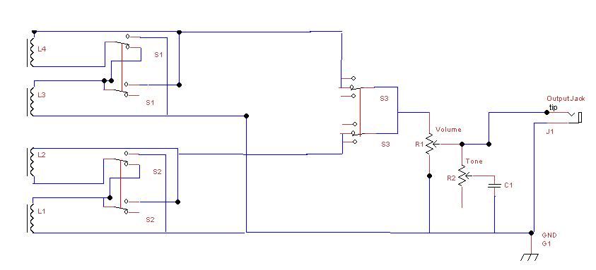
the outputs resistance to earth is constant ie 500kohms=the other pup sees 500k to ground regardless of this pots position, only it's own pot can reduce it's resistance to earth
Actually the output sees 250k to earth when both pickups are selected (the 2 500K in parallel but I am just being pedantic) But Borge you are correct. I have modified a few Gibson's and Epiphones and they work like that with independent volume controls!
My advice to all those who keep referring to wiring LAYOUT diagrams. Draw out or refer to CIRCUIT diagrams as I posted above. It is far easier to work out and understand what is happening.
Keith
-
Here's the circuit diagram for independant tone and volume:
-
Pretty sure its African Mahogany.
What have you done with the "art"?
I see that stuff all the time around here with high price tags to sell to tourists. It is really terrible. Don't understand what the tourists see in it.
There is lots better real African art around. Look out for the Ndebele art. We had a Ndebele artists finish off some of our Afri-Can Guitars and I believe Billy Gibbons has one now. Not sure how true that is though.
Keith
-
Buy a small power supply they cost around $10. Will be much safer and less work and probably cheaper than building your own.
From your question it doesn't seem to me you know the basics of building a power supply and messing with mains power can kill you!!!!!!
Keith
-
But I did not understand the capacitors' function in tone control. If I now understand correctly, every potentiometer is nothing more than a volume control in itself. (Or to be more specific, a blender of 2 possible signals, one being full volume and the other being nothing.) But when you add a capacitor to one 'end' of a pot, you're basically adjusting the volume of that capacitor's specific impedance against the total/complete audio signal.
Well sort of. There is only 1 signal though. In a potentiometer for a volume control it is applied across the resistance of the track with one end being at ground, usually. The wiper moves across the track and forms a potential divider which taps off the output depending on what the ratio of the two parts is. This will vary from 0:R to R:0 and all possible ratios in between where R is the value of the pot.
A tone control is a variable resistance in series with a capacitor such that the total impedance is R + X where R is the resistance value and X is the impedance determined as I explained above. So changing the R will determine which frequencies get passed through.
Do the EQ knobs on an amp or stomp box work the same way? Just a chain of pots of various values with different sized capacitors attached to them?Yes
Is the use of capacitors the only known way to alter the EQ of an analog audio signal? Or are there other wiring methods that will achieving the same result?No capacitors are not the only way. You can use an inductor as well. Inductors are the inverse of capacitors ie X = 2 * pi * F * L the impedance increases with frequency Capacitors X = 1/(2*pi* F* C) (I forgot the C above) However inductors are usually formed by coils of wire which can and do pick up noise induction from around them so are generally avoided as far as possible.
-
One more questions about the use of potentiometers: I understand that higher rating pots allow a wider frequency range towards the higher end to pass through. But if you are using multiple pots of different ratings in your circuit, is the audio signal result always going to be reduced to the lowest-rated pot? For example, if I have a circuit of 3 pots: 1M + 250K + 1M ... does the use of the 250K pot in the circuit automatically nullify the 'benefit' of the 1M pots by reducing the entire audio signal output down to 250K?
It depends entirely on the circuit design.
For example a tone control circuit in an amplifier could use both pot values along with a variety of capacitors and resistors to give a suitable tone adjustment. There is no 'benefit' of using 1M or 250K or whatever. It depends entirely on the ear of the listener and what the designer is trying to achieve.
Potentiometers are purely resistive components ie they do not have a frequency dependent component (not at audio frequencies at least) In order to use them as a tone control, as in a guitar, they have to be coupled with a suitable capacitor to form a variable filter. Capacitors have an impedance determined by their value X = 1/(2 * pi * f) ie the higher the frequency (f) the lower the impedance.
Keith

Squier Affinity Tele Upgrades
in Solidbody Guitar and Bass Chat
Posted
Just consider the physics of the two methods:
The string tension in the top loader is directly attached to the bridge which it is trying to pull out of the guitar. Well most of the force is horizontal but there is a vertical component to the force too.
The string through takes all the tension directly into the body and the strings loop over the bridge saddles. There is very little tension on the bridge horizontally ie in the plane of the strings BUT the vertical (90 degrees to plane of strings) is down into the body thereby pushing the bridge plate tighter against the body.
For the same scale length and string gauge the string tension will be the same. It is the direction of the force vectors which make the difference on the bridge. So I don't see top loading being easier to play, there being very little difference between the overall string length between mounting points.
Keith