


ansil
-
Posts
1,419 -
Joined
-
Last visited
Content Type
Profiles
News and Information
Tutorials
Product Reviews
Supplier Listings
Articles
Guitar Of The Month
Links and Resources
Forums
Gallery
Downloads
Posts posted by ansil
-
-
Shirt answer yes.
-
very good and clear dpm99 there are tons of things to do with an fx loop. i had a bi amp rig that i was using an old fender champ that was ss but had blown its output ic and was prone to overheating. it sounded like carp on its own but through the headphone amp out to the fx loop in of the fender bass amp i was using it was god like.so i would use the chorus to split my guitar signal into both amps. and use the fx loop like a channel switch since it had only one channel i would set the clean tone up normal to get good guitar tones and use the eq on the champ to get good rhythm tones and a switchable graphic eq on the end to get good lead tones. since i did not use the fx loop send only the return. the master volume was set by my champ for dirty and by the master volume level on the bass amp for clean. it was a nice little rig i miss it. i used it for a couple years for dream theater and vai type stuff.
-
simple fet buffer trim pot blen mounted on piece of plastic by the pickup itself.
-
with a screwdriver and a little patience yes you can make the tone pot do double duty. but as far as those cap values. go you realized that you are utilizing a larger cap for the humbucker which has more midrange and lo mids than single coils right? single coils tend to produce much more low and high end than humbuckers that is something we lose when using the humbuckers we love so much. F= 1/(2PIRC) if you plug in the values for your VOLUME pot as R. and your Capacitor as C you will find your freq or F. also here is a calculator online to show you. http://www.muzique.com/schem/filter.htm i didn't see your volume pot value list so i will do the common values. at 500k and a .022uf cap your freq roll off point is at 14.5hz which is more than 3 octaves below the fundamental freq of the low e string which is 82.4hz. for a 250k pot its 29hz which is a little over two octaves below the estring and for a .047 you roughly just half the freq i listed above.
now the reason for this long explanation is that if you were to set a slider on a graphic eq all flat and pull all freq except 14.5hz to down -18db or better and then panned the output of that between your regular guitar signal and the eq then you would have a good comparison on what the tone control is doing to your signal. it really matters very little on the size of the tone pot other than the spaces between 0-100 a one meg pot will give you a wider throw than a 10k ie the spaces between are a bit easier to hit. but it is not a movable filter ie when you turn the pot down just a little it isn't changing from 0 or 10 just the volume of the filter as the filter is made between the parallel combo of the cap and the volume pot as its the constant resistance to ground. now you can change the layout of your guitar and make it a variable eq which is quite easy with a wire switch and is very usable. but i digress. if you want to do both pots and have middle neutral then you will need a 500k or 1M preferable linear pot. disasemble the pot and at the 50% POINT either put some fingernail polish or simply cut the trace on the horseshoe of carbon on the pot wafer. now when at 5 or the middle it will not conduct the guitar signal to the caps to ground. put a cap on either side of it and there you go the circuit you need after all the bs rambling lol.. btw here is how i did it on my jem wiring you probably want to just ignore most of the schematic and look soley at the tone control. also i added trim pots to the pot inbetween the caps and ground as to vary how much of the cap will go to ground. just like a normal tone pot but with the capability of finding the sweet spot easier.
 to clear up any confusion on my crazy a$$ wiring diagram the aqua colored wire is from the pickup switch. the brass colored wire is ground the pot on the right is the volume pot showed upside down as you would see it in the guitar cavity or the pickguard. the two caps are for my freq responses alone that is why there are no values. as far as the resistors go i didn't have a stock photo of a trim pot so i used a simple resistor however you can use a fixed resistor if you like and yes the middle lug is grounded out see with the magic pot installed here i put a small pie shaped wedge in the carbon at approximately 40-60% rotation so it doesn't have to be dead in the middle to dropped out of the chain but once it is there it acts like a no load tone pot only in the middle lol. check out the wonderful tutorial on making a no load tone pot on this forum here. http://www.projectguitar.com/tut/pots.htm also look into the secret life of pots by rg keen at geofex http://www.geofex.com/article_folders/potsecrets/potscret.htm hope this helps. also if you need anything feel free to post i might even have a pic of my tone control somewhere
 -
i dont' have a drop box account sorry just email me ansilgregory at yahoo dot com .......... i will have to dig it out of my email. its not really that complicated to build. it actually could be done inline instead of using that big azz box they use six buffers into a 13 pin din could be built on a pencil and then epoxied. the piezo tracks better i just never liked buffered pickups either go active all the way with filtering and gain stages and such or go home is what i say lol. you can also do a non buffered version with led photo fets tracking the strings
-
in the rmc unit that was in my brian moore the 13 pin provided power, up and down for patches which never worked with roland stuff at least not mine. and buffered pickups ie magnetic and buffered individual piezo output. i don't know about you but the buffered guitar part sounded like crap i always ran the guitar as a midi synth and used the guitar output for guitar. but a hex buffer for the hex pickup could be done with a hex inverter since it was a non gain device. or 3 dual opamps or a quad and a dual. i still have the rmc stuff from brian moore if you like a copy
-
there are other options they make special pots with push pull on them and they can be double and triple ganged pots http://www.mec-pickups.de/englisch/pages/09_pots/index.htm
-
why not just build your own roland unit to hook up the unit too. there is a great selection on diy hex pickups on google thats where i found how to build mine
-
well never mind guys i didn't get any feedback and its done now so it doesn't really matter
-
actually you can get some really nice replacement pickups that are that are quite good for pennies on the dollar. ibanez v series pickups. they go on ebay for next to nothing and i have used them for years before moving on to active systems. sometimes incorporating them into the active arrangement
-
fair enough just wondering i like to see circuits. i don't do buffers lol
-
so wheres a schematic of this critter at i would like to see it
-
i meant to ask did you make the pcb yourself cause its quite tasty looking from what i can see in the pics very professional.
-
Yes, that looks familiar. You can change the current setting of the LM4250 also to open up the top end. Same idea as early MM preamps. If the LM4250s weren't so expensive compared to TL0x2s and other similar op-amps i would have used that myself. Great lil micropower chip.
not to be rude but are you outside the usa? they are around a buck each
ok i am an idiot i didn't check profile before i asked lol sorry
-
Which schematic do you have? Those buffers are a little different to these. Same kind of idea though.
this was the one over at freestompboxes.org its been verified and the old one i tore apart was pretty darn close from what i salavaged from my first emg teardown ie destroyer
this is also a similar version to what i am using in my mini 81 on my wiring diagram minus a few parts swap
-
EMG, et al. have them hidden in the pickup itself, so it is surprisingly common! This does not "model" the tone like EMG says theirs do (long story) but certainly quietens instruments and drives cables without losing top end.
i would be interested in hearing that story, i am trying to see what the differences in the preamps are i have the 81 schematic.
-
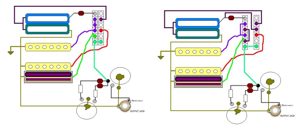
what do you guys think of this wiring diagram.
Seymour Duncan sh-2 jazz neck
Dimarzio single coil nice wide flat output balanced pole pieces
fender single coil Texas special slight over-wind with staggered pole pieces
mini emg-81 . although they don't make an emg-81 in a single coil package but, i found a hot rail style maker with a similar wiring and ceramic magnet. so i copied the circuit.
for those that don't want to take the time to look at the schematic
5.Duncan with cap mod
4.dimarzio and CC Duncan
3.dimarzio
2.dimarzio and fender singles
1.MINI 81
5.Duncan with cap mod
4.dimarzio and CC Duncan
3.Duncan no cap mod and mini 81
2.dimarzio and fender singles
1.MINI 81
some will wonder why i don't just coil cut a hum bucker in the bridge however i don't really like many passive bridge pickups. if i find a good one then to me it doesn't sound good coil cut to me. So i figured for my playing style I use the bridge pickup for ripping out leads and melodies. most of my solo stuff is on the neck pickup. clean stuff is always single coils so one of these schematics is going to do the job. let me know what you guys think. thanks
also i forgot the tone pot is a linear taper pot that has been turned into a no load pot but its zero point is in the middle so one way is a smaller cap for slight treble roll off and the other is for a deeper roll off and in the middle is out of circuit.
500k vol, and 1 M tone
-
f=freq
r=resistor
c=capacitor
F = 1/(2*Pi*R*C)
capacitor is obvious but most peo0le think the tone pot is the resistor but its not its the volume pot. so you can figure where you want the freq range to reside in. fundamental freq is 82.4hz to aprox 1.35khz after that its all overtones and undertones i generally go around 600-800hz i only like subtle roll offs. that or big fat honking ones like a .1uf cap.
also try looking into some of the mods posted on this site. i posted many myself on inline caps. and there was one {although i don't know if it was on this site or not} that had the tone pot pulling double duty. one side fed signal through cap to output jack the other fed it to ground. it was quite interesting.
-
This is a program I got off the Roberto-Venn website. It's very useful for making wiring schematics:
looks really cool thanks
-
what about a peavey nitro pickup. they are smokin hot. fat sounding tonally and four conductor for plenty of options.
-
Side question: for those that use shielding paint often, is it robust enough after 3 coats to use AS my grounding medium? IE: if I attach a lead to the paint and the paint touches all my components I shouldn't have to ground each component's housing? Or more importantly, maybe I SHOULDN'T wire-ground each component because it could cause ground loops if already grounded by the paint?
Thanks,
Chris
i have used some really good stuff a few times but it is at my luthier friends shop and he isn't telling me whats in it as its a special mixture and was not designed for guitars. on the other side i have purchased many many products from stewmac and industrial suppliers when i ran a full size shop in the back of a record store. the short answer is this solder all ground connections to a ring and screw it through the paint to the wood. i did it in a Yamaha and it worked fine. long answer i own two Parker fly's both seem to use the same shielded paint and are relatively noise free, notice i said relatively. the green fly is now shielded with copper and by by noise. i was worried it was the active preamp going bad so i swapped them and nope. its just the paints ineffectiveness compared to the copper.
-
if you used the three way wiring for two pickups on a five way like shown. most switches won't work. also if you used one of those crazy stewmac switches that have a preset strat wiring diagram they have only recently fixed the link for its internal wiring. for about a year there seven lug switch for strats was made completely wrong from what they showed in the wiring diagrams. i still have one of the bad ones it was quite a pain in the arse. check Seymour Duncan website they have the clearest schematics i have seen in years
-
 1
1
-
-
so, I got an old beater off Craigslist, and the fellow who had the guitar had been trying to edit the pickup situation. when he parted with the pieces, I got p-90's, but not the screws and springs used to mount them. I am google-failing to find a source where I can get just the springs and screws without the pickups.
anyone willing to edumacate me?
thanks in advance, and yes, I am a total newbie.
depending where your at your local hardware store. you may not find the exact head style but at ace hardware here in the south i have found pickup screws pick guard screws you name it i have found it. also in Cleveland we have beattes same principle but family owned mega hardware
-
true but logically speaking that kind of falls in the envelope category only because it has to detect the nuances from the guitar. which you can typically find on the net a simple flow chart for standard pedal arrangement. anything that is a filter or envelope type device needs to see the pure guitar signal. ie good harmonizers envelope filters/followers wahs [wahs are more subjective some people like them after everything else] gain devices boost od distortion etc.. modulation fx then time base fx.
there is no set rule but common sense will tell you if your trying to use an effect which drastically alters the sound as much as an acoustic simulator really anything modeling at all should go first. but then again you get some cool sounds by not doing it in any set pattern. i have an on board oscillator that i use on a push pull switch in my guitar and it goes before everything, but it produces a nice fat rectangle wave so i have to pad it down before it hits the amp. but i also have a boss feedbacker clone where the dry signal come in but doesn't leave. so only the effected sound comes out with a cool mod to track the input i can take the input signal and trigger the foot-switch to hold the effect in the octave mode so slightly after each pick attack a variable swelled octave rings out. so all you hear is the effect. comes in handy when your playing acoustic or classical and have a haunting lead come from no where. so in essence it all depends on what sound you are going for. this is why i have three seperate pedal boards

A Switch For Two Different Tone Caps Sharing One Tone Pot
in Electronics Chat
Posted
Yes if you look at the secret life of pots you will see 50% is actually 50%