


Strandberg Guitarworks
-
Posts
129 -
Joined
-
Last visited
Content Type
Profiles
News and Information
Tutorials
Product Reviews
Supplier Listings
Articles
Guitar Of The Month
Links and Resources
Forums
Gallery
Downloads
Posts posted by Strandberg Guitarworks
-
-
Looks great, would love to be able to mill custom bridges.
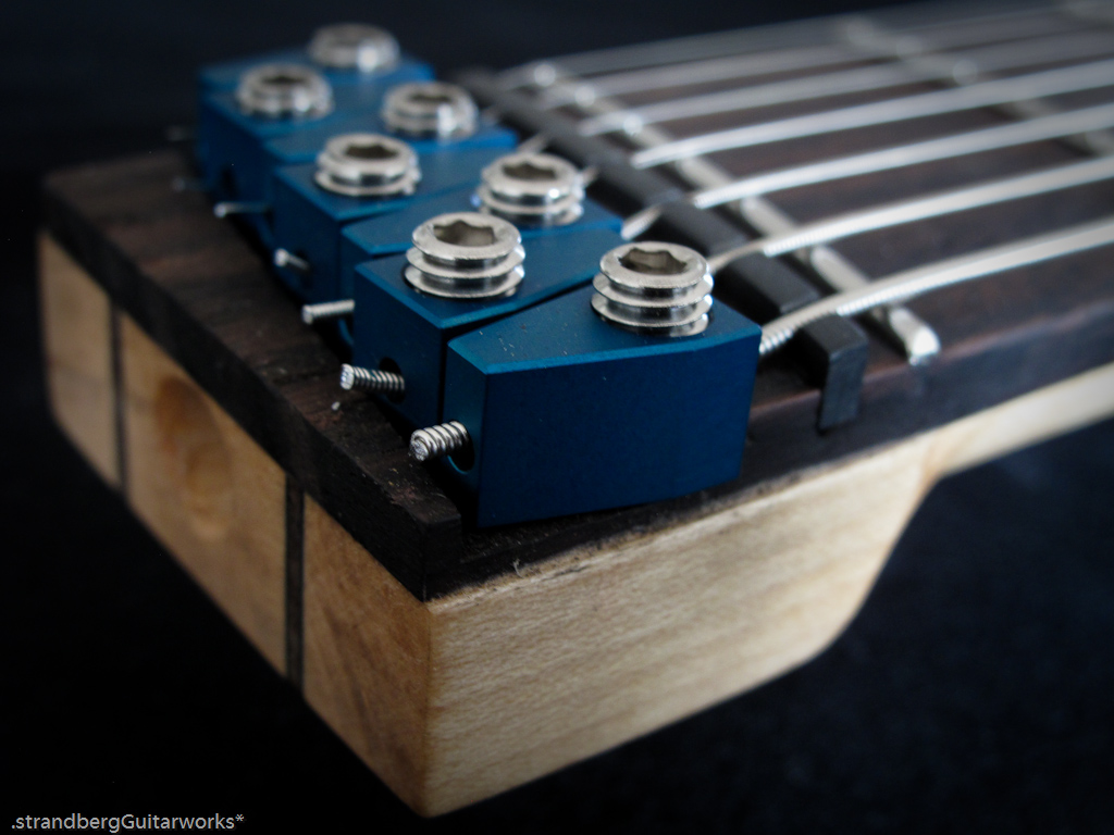
Why do the groves for the tuners thin out on the middle strings?
My guess would be for a radiused string height, like a TOM-bridge has..
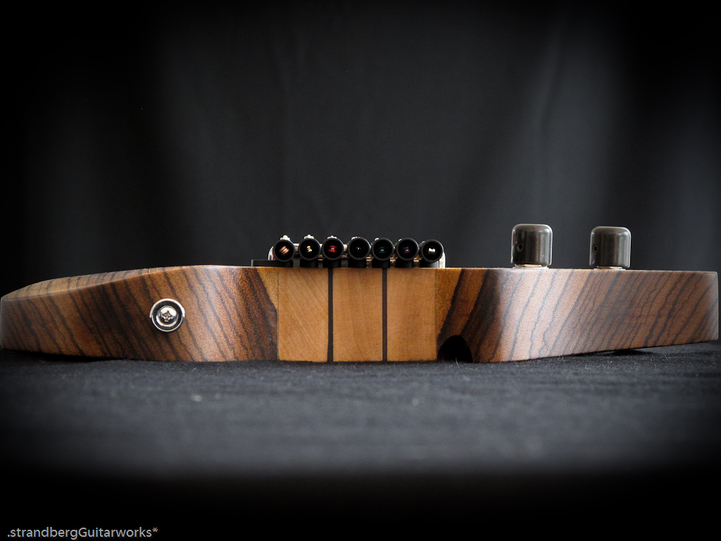
@Cactus - you're right. It has a 16" radius. Previous revisions of the trems had "steps" and equally deep grooves, but I think this looks better.
Note that each string has individual height adjustment as well.
-
damn !
looks perfect !
do you sell those or it's just for your builds and your needs ??
I am indeed planning on selling these! I have been looking for an alternative to knife edges for a long time and have been sold out of the regular tremolos, not wanting to commit to ordering new parts, so am very pleased to arrive here.
-
So, here's a completely different kind of build - hopefully to the general interest!
I have spent the weekend at the mill and lathe constructing a new headless tremolo.
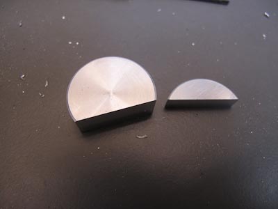
6 mm aluminium to begin with. I am doing a 6-string and a 7-string in parallel, which is the reason for the two different size pieces.
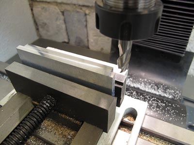
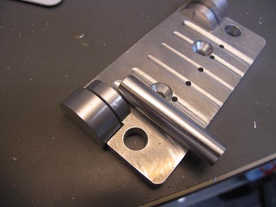
Here, I have routed the grooves that the tuners will sit in (on the 7-string)
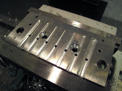
The two base plates, almost finished
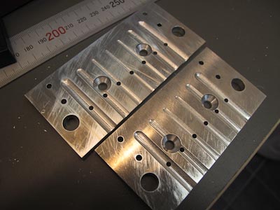
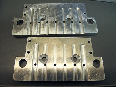
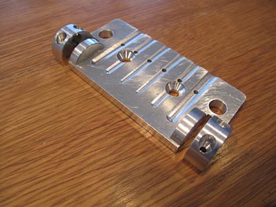
Plates completed
This is what brings it all together
Almost there...
And assembled!
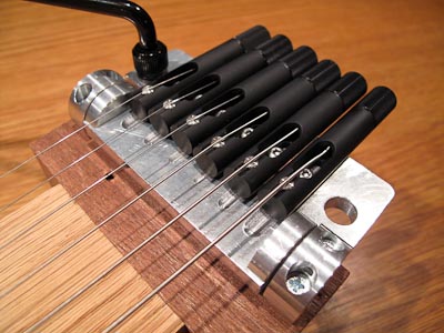
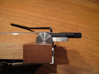
What's interesting with this tremolo is that it is based on needle bearings and has two options for fulcrum points. One give more extreme action and the other is much smoother. More pictures will follow! I am sending them away for engraving of logo and then anodization.
-
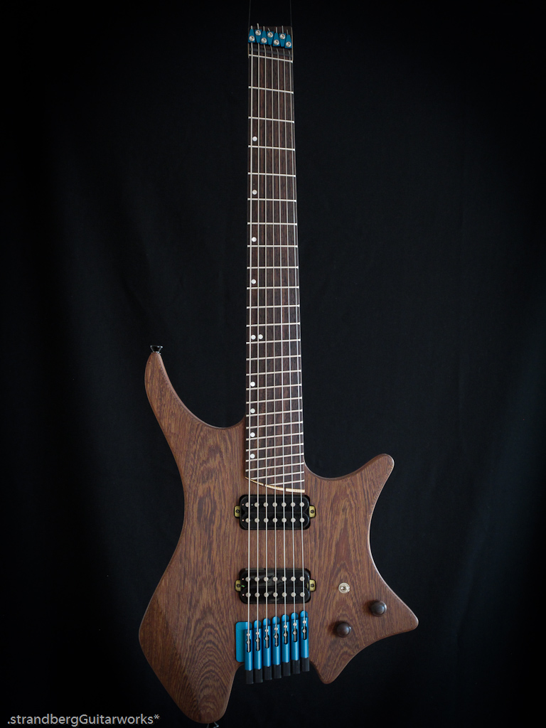
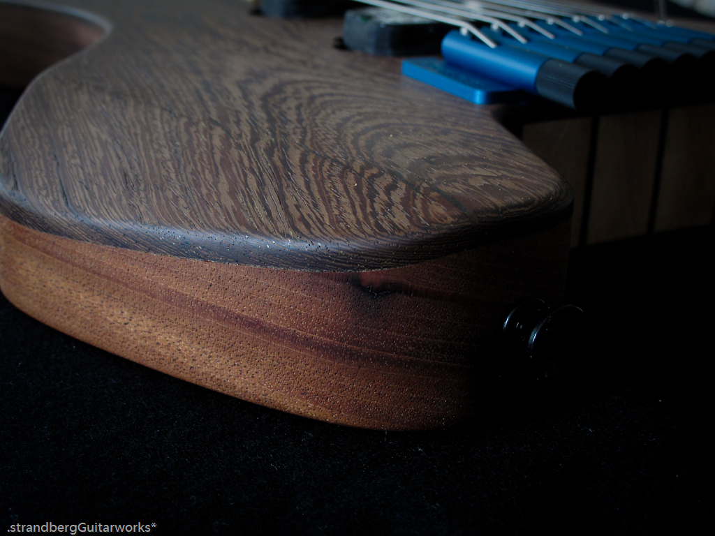
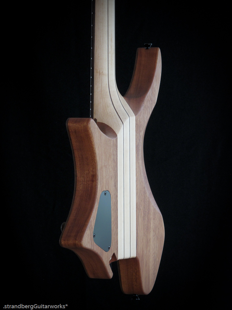
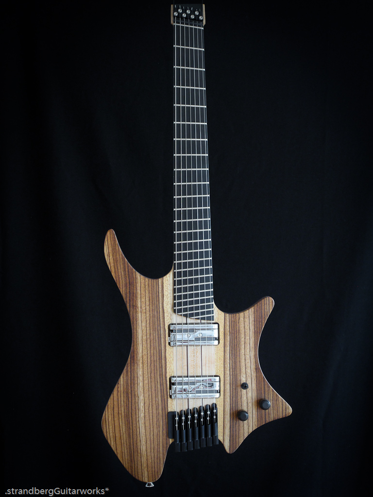
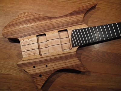
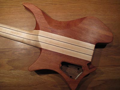
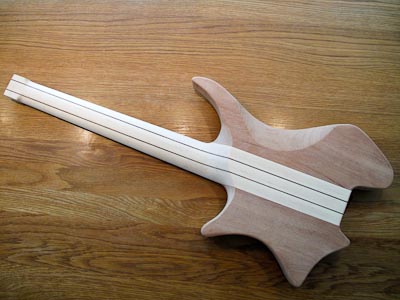
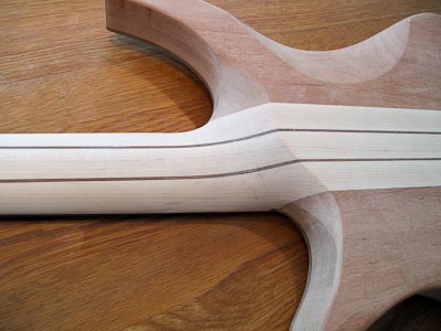
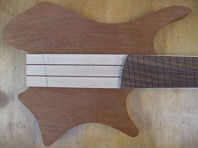
Here's "#5" - another installment in the Ergonomic Guitar System
Mahogany back, chambered
Wenge top, book matched w/ white veneer strip
4 mm radius edge
Belly carve + arm bevel (Wenge top bent to fit)
Oil finish
2 x Lundgren M7 pickups
2-position selector: Neck/Bridge
Master volume, master tone
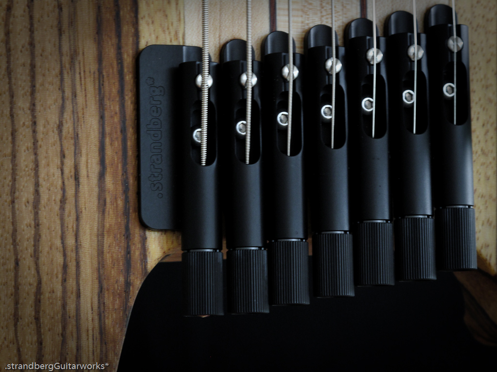
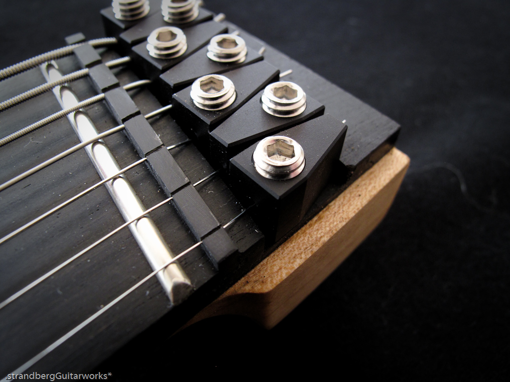
Strandberg EGS Series 3 fixed bridge and string locks, custom color blue
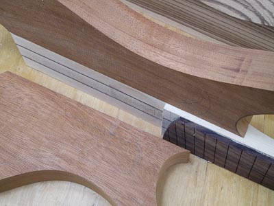
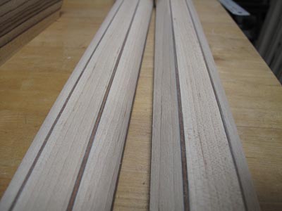
3pc through body maple neck with 2 x mahogany and 4 x carbon fiber laminates, double-acting truss rod
25.75” – 25” scale
24 medium/high stainless frets
Rosewood fretboard
-
Check out log of produced instruments including those for sale at http://guitarworks.thestrandbergs.com/instruments/
-
If you live in the San Antonio, TX area and want to try #3, give me a shout! I am there between today (10/10/10) and (10/13/10).
-
I have created a step-by-step guide on how to plan and build your very own Strandberg Guitarworks EGS guitar.
http://guitarworks.thestrandbergs.com/2010...diy-egs-guitar/
-
I just realized that this guitar is in an 8 string thread, but has 7 strings.
Aside from that, it looks really nice!
Hehe... it started as an 8-string thread but evolved into just a 7. Sorry to disappoint :-)
-
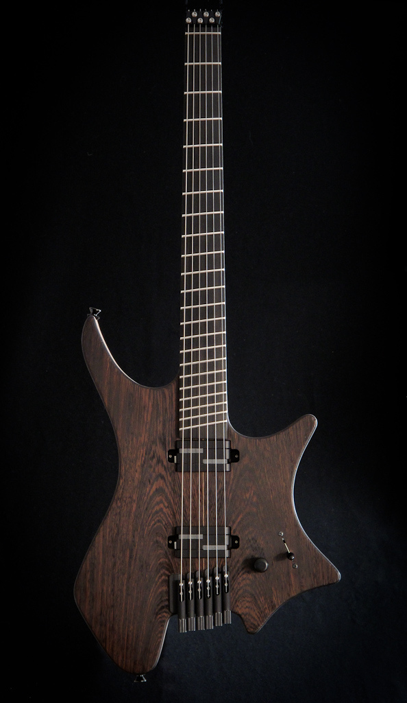
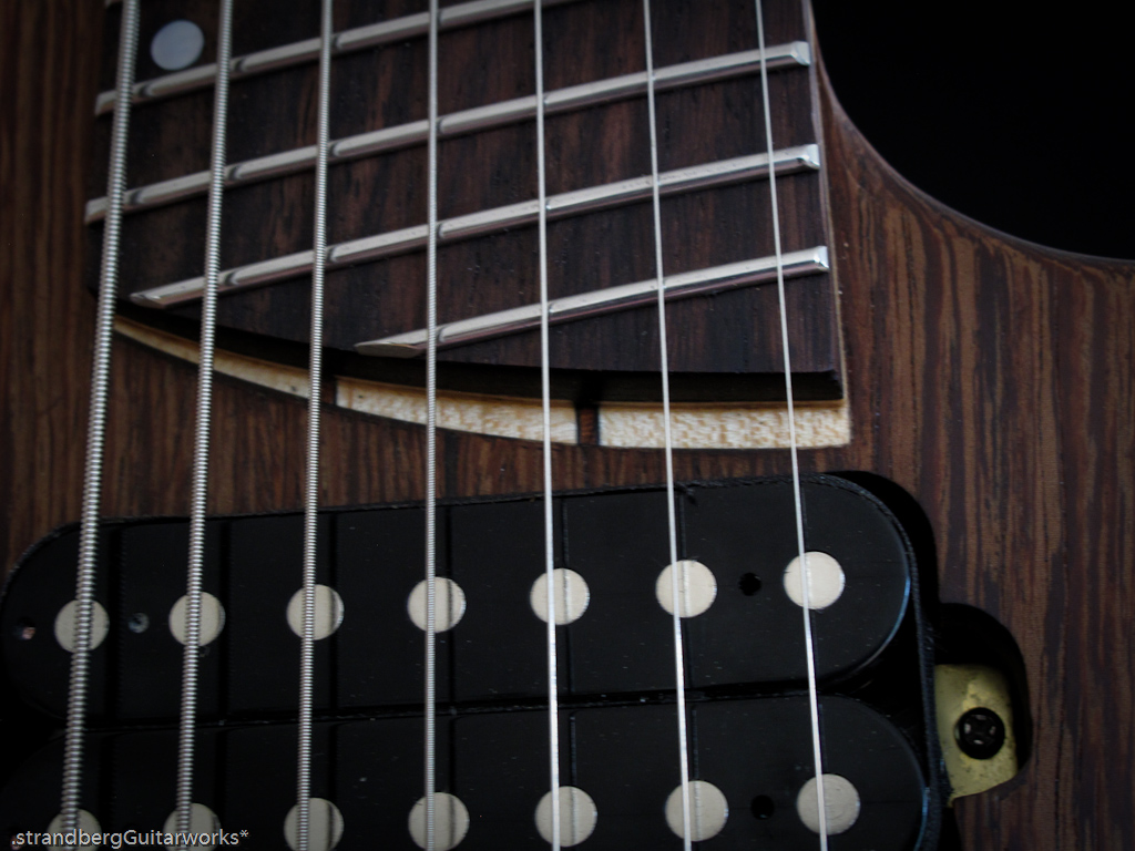
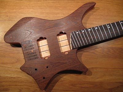
So which pickups are those, the p90's or the bass bars?
They are the P-90s. I have been curious about the Bass Tone Bars, but they seem hard to find, at least when I tried.
-
Removed almost commercial content....
-
It's done! Will post more when I have caught my breath.

In the meantime, there are plenty of pictures on my facebook page.
-
Done!
Many, many more pictures on my facebook page http://www.facebook.com/strandbergGuitarworks
Will post the full specs when I have caught my breath....
-
after the first few coats of oil
-
Waiting to dry...
-
First stringing up to verify function:
-
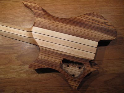
So, here is some more progress. There are 18 pictures in total on my site, all of which I will not re-produce here.
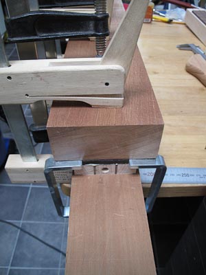
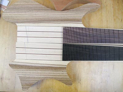
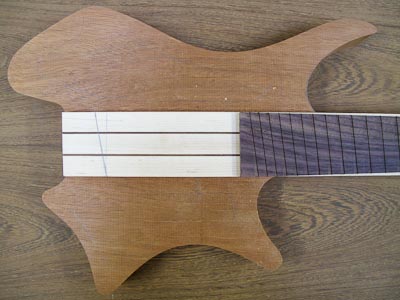
Here is the neck set cut with the router shown above
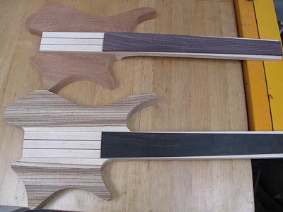
And the neck shape (right one is my other build)
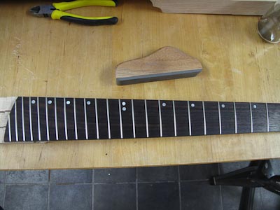
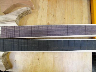
Fretboard shaped and inlaid (and fretted of course)
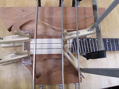
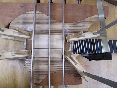
Gluing the sides
I am doing things in the following order:
- glue laminates of neck
- band-saw away and shape section on underside of neck portion
- insert truss-rod (while sides are straight and can be used as guides for router)
- shape contours of fretboard (so that it can be used as a router template later)
- cut fret slots (while it’s still thin and easily fitted into the slot-cutting jig)
- glue fretboard (while it is flat so that it can get optimal clamping pressure)
- use router to shape contours of neck (using fretboard as template)
- rough shape back of neck
- radius fretboard
- finish fretboard (add inlays) and fret neck
- glue sides (and top)
- finish shaping
- sand
- sand
- sand
- rout cavities for controls and pickups
- sand
- sand some more
- finish/polish
- done
So, it’s an easy 20-step process.
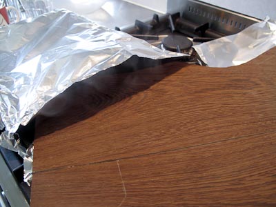
Steaming the top prior to bending
and clamping it into shape
- glue laminates of neck
-
Some more build progress below. There are 18 pictures in total on my site, all of which I will not re-produce here.
Neck set
Weight removal (almost 250 grams) in a novel way
Neck shape (left is Chris Letchford build)
Gluing sides (finally!)
I am doing things in the following order:
- glue laminates of neck
- band-saw away and shape section on underside of neck portion
- insert truss-rod (while sides are straight and can be used as guides for router)
- shape contours of fretboard (so that it can be used as a router template later)
- cut fret slots (while it’s still thin and easily fitted into the slot-cutting jig)
- glue fretboard (while it is flat so that it can get optimal clamping pressure)
- use router to shape contours of neck (using fretboard as template)
- rough shape back of neck
- radius fretboard
- finish fretboard (add inlays) and fret neck
- glue sides (and top)
- finish shaping
- sand
- sand
- sand
- rout cavities for controls and pickups
- sand
- sand some more
- finish/polish
- done
So, it’s an easy 20-step process.
- glue laminates of neck
-
..snip..
I was wondering what problem are you trying to solve with the carbon rod? Are you trying to stiffen the neck or maybe add some resonance with a chamber?
In my experience and this is strictly opinion I have always felt that really stiff carbon reinforced necks don't resonate like a neck without carbon rods. I like to feel the guitar vibrate in the neck while I am playing. I am not condoning building a neck that flexes but I won't use carbon rods.
If you are adding the rod to gain a hollow area in the neck and reduce weight then I want to know how this turns out. I have been toying with the idea of chambered necks for a few years and would be interested how that turns out.
Thanks for sharing. I get so many great ideas from you and Rick it is amazing.
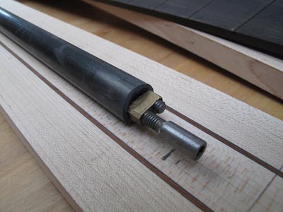
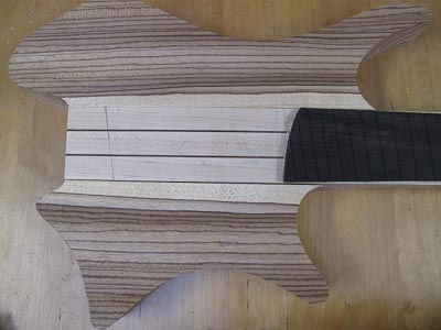
The primary goal for the carbon is to stiffen the neck in a way that it allows me to remove weight inside it. In this particular instance, the weight of the conventional truss rod was so high that the air introduced in the neck didn't make a difference, and the geometry of the neck laminates didn't really allow cutting any additional sound channels (i.e. air pockets).
Secondary goal is that have found that this carbon tube arrangement has resulted in a very uniform tonal response across the neck, completely free from dead spots. This needs more evidence to be proven, but I have high hopes.
Cheers,
Ola
-
I'm thinking that the rod running inside the tube will be similar to it running inside a routed channel, so it shouldn't make a difference with the expansion?
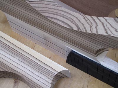
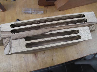
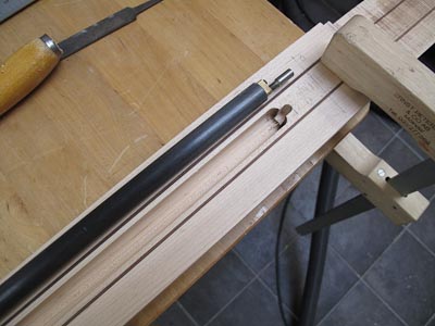
Chris: it is secured against rotation by the threaded brass sections on each end of the rod sitting in 6 mm grooves just like they normally would. It doesn't show in these pictures, but I squared off the channel with a chisel.
But... I'm just as nervous as you guys. We'll see how it works out!
-
Truss rod mounted
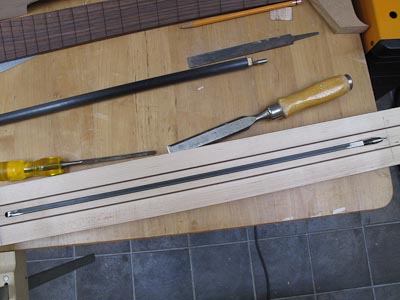
Truss rod adjustment
New shape for fretboard heel
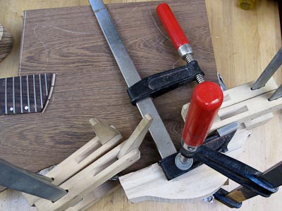
And workshop addition...
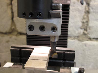
I got this to create the neck angle from the body end and it works like a charm.
-
Truss-rod experiment... Combining the CF tube that I had on #3, which worked out really well with a conventional double-acting truss rod. For more details, see main site.
Truss rod adjustment
And new fingerboard end
And on a side note, I just got one of these
I used it last night to cut the angle of the body end of the neck. It works really well.
-
Hi Plinky,
if you are outside the EU (which you probably are since you did the calculation in USD) the price excluding VAT is roughly $450 at today's exchange rate. Still not cheap, but it has several unique features (will skip the sales talk here....)
Cheers,
Ola
-
Some more progress:
-
Some more progress - will get back to you on Zebrawood weight, it is fairly heavy. I get my CF from Epotex, Gunnar Swärd is incredibly helpful and good to deal with.
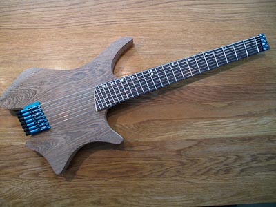
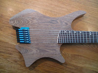
14-stringer anyone?
And you can download the FUZZ article here, it does indeed feature this neck blank.
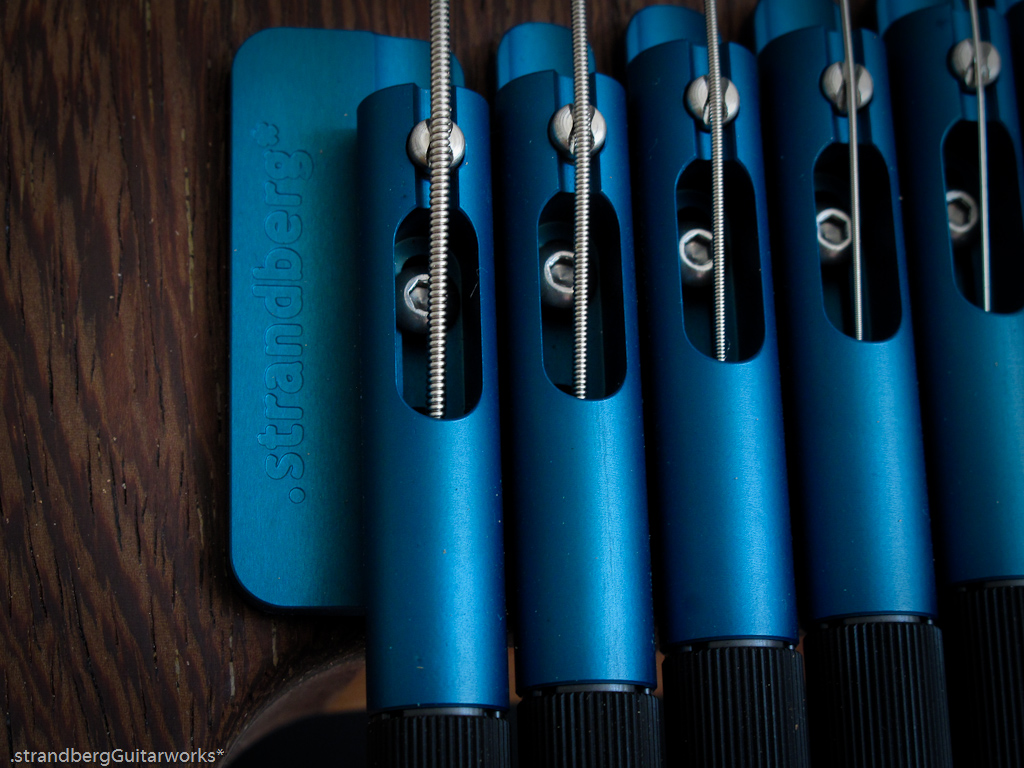
New Headless Tremolo Build 6-,7-,8-string Needle Bearing
in In Progress and Finished Work
Posted
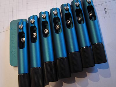
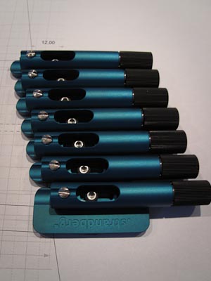
I got the parts back from the anodizer the other day. Here's how they turned out:
Here's how the Dual Action works - on the left (the 6-string tremolo) you will note that there are two positions for the bearing and shaft. This allows you to change the behavior of the tremolo from stiff and extreme to smooth and subtle. The 7-string tremolo on the right has only one bearing due to the extra force applied from the string tension.