


Fresh Fizz
-
Posts
134 -
Joined
-
Last visited
Content Type
Profiles
News and Information
Tutorials
Product Reviews
Supplier Listings
Articles
Guitar Of The Month
Links and Resources
Forums
Gallery
Downloads
Posts posted by Fresh Fizz
-
-
I'll have to check on that. I doubt it is the input jacks, as volume adjustments have no bearing on the hum coming out of the speaker. It is constant. Star grounding would be a good idea, though. I think I'll work on that. Actually, I'm contemplating knocking together the Bassman mod posted earlier in order to "start from scratch" so to speak, and then gradually transition it to more of a SLO-type (opposites, I know). In this case, I would do my grounding all via star ground and save myself a headache or two.
The most likely is that your power valves are not a matched pair. They draw different currents at rest. As a result of this the remaining hum after rectification isn't cancelled out at the output transformer. You can check the currents through the power valves by measuring the voltage across the cathode resistors (& no input signal) and applying Ohm's law. Should be somewhere around 35 - 40 mA.
2 solutions: use a matched pair of output valves or use some bias circuitry with a trimpot per valve.
cheers,
FF
-
That's good to know. I'll look for one of those straightaway.
I just compared the schematic to the actual machine, and it appears that the rectifier RC1 is missing. This is probably not a good thing (I think its part of the bias supply).
It's a miracle that nothing burnt through. Is it because of the valve rectifier (GZ34)? Are the kathode resistors bigger than 1 ohm (some kinda class A setup)?
The 5F6A bias(& power) conversion should solve your problem when using 5881s.
Since you're experimenting with 6L6s the bias setup requirements could be different. I'm looking at a Fender vibrolux 6G11-A schematic. It has 365 volts at the anode and -36 volts as bias input.
FF
-
So you're the owner of a Dukane 1c460. (PA, rackmount)
I found something of the Dukane 1u460. (PA, head)
So you need to check if it's based on the same schematic.
I wouldn't be surprised if your Dukane is the result of a u46025F6A(Bassman) conversion that went wrong.
If I have understood it well the flickr link provides enough info to get the Dukane working as a Bassman.
cheers
FF
-
@psw
Col's sandwich stack and my version deal with another issue, the big difference that exists between signal levels in driver and sensor mode. The combined sandwich drivers have a hum cancelling effect on the sensor coil. This should greatly reduce the interference of the decaying signal across the driver coils (right after the switching) with the signal across the sensor coil.
Well...could you expand on this aspect then because I'm not understanding I suspect.
To me there seems to be a logic flaw. If a driver is putting out enough EMF to move the string, any magnetic sensor is going to sense this fluctuating EMF resulting in oscillation or squeal, no? If the cancellation of the two driver coils is complete, then there will be not enough EMF to move a string surely? I can kind of see the idea of having the two drivers separated but my experiments in sandwich designs and similar things never could overcome this kind of intrinsic quality problem...
I'm not that keen on studying patents these days either, though the referencing of the Moog thing and not studying it for at least the 10 minutes it took to get the general gist of it and see that there have even with this information some false assumptions seems neglectful. The basic thing is much as I described and proposed years ago, sample and hold and activating things exactly as described in the "driver engine" idea so that interactions that they describe between close drivers and sensors are eliminated through the sequencing of activation.
I mentioned the name Moog like: Moog did it so we could do it. The false assumptions are yours. I spent more than 10 minutes on the Moog patent and watched several YouTube clips to get an idea of its performance. I'm not familiar with your "driver engine" idea, but if you say that it works on the same principles as the Moog then why you don't understand?
FF
-
@psw
#1: My road to success is trial and error, develop some basic idea, build an early prototype and then figure out why it doesn't work.
 I'd rather not study patents, too boring.
#2:'Our old school' sustainers make use of 2 separate transducers (driver and sensor) which operate continuously.
The Moog kind of sustainer uses only one transducer. But the transducer cannot do both functions at the same time therefore this kind of sustainer needs a technique to switch between the two functions.
Col's sandwich stack and my version deal with another issue, the big difference that exists between signal levels in driver and sensor mode. The combined sandwich drivers have a hum cancelling effect on the sensor coil. This should greatly reduce the interference of the decaying signal across the driver coils (right after the switching) with the signal across the sensor coil.
#3: Well, the goal is mentioned in the topic title. Figure out how it could be done and then ,if possible, build it.
Hexaphonic is always an option but in an experimental stage you want to keep it as simple as possible.
#4: ?
#5 and 6: No need for improvement! Going fishing all day isn't better than going to a shop and buy a fish. Same goes for carving a bear out of wood instead of watching a real one in the wild.
Cheers
FF
-
Thanks for the replies guys. I myself have a lot of doubts if this could work. But as RM2488 mentioned it's already been done by Moog.
So it's theoretically as possible as me building a guitar and winning the GOTM competition.
Some of the issues mentioned I even haven't thought of.
I want to share some other idea I have after reading your comments.
One idea I've mentioned in the past that could help here is to create a sandwich stack. (yep, more brainstorms I'm afraid)You'd have 3 coils:
one main 'pickup' coil - a low powered pickup coil, but still many more turns than a driver coil
two small driver coils, each identical, one on top of the pickup coil, and one on the bottom.
The idea is that you feed an opposing drive current to the lower coil.
The symetry of the two driver coils with respect to the pickup coil should cancel much of the drive signal current that would otherwise be induced in the pickup.
At the same time, the asymetry with respect to the strings should allow the top driver coil to still drive them and provide sustain.
(there was something tricky going on with the core structure as well, but I don't remember the details exactly)
"..."
The bit I'm least sure about is: Does the cancellation property of this sandwich stack idea mean that the relatively high inductance of the pickup coil doesn't slow the response of the magnetic circuit down?
What I am thinking of is using 3 coils. Two driver coils (bifilar wound) and one sensor coil. Both driver coils have their own driver amp. One of the amps has the signal inverted (inverting opamp, coil leads swapped).
The switching should work like this:
1. driver mode: 100% non-inverting amp, 0% inverting amp
2. sensor mode: non-inverting amps switches to 50%, inverting amp switches to 50%.
PRO's(?): no single driver coil that runs idle (100% to 0%)
side effects of switching up & down should offset one another.
If the level of the inverting amp exceeds that of the non-inverting amp there should be string damping.
Cheers
FF
-
But it sounds too fat, so, I decided to mix the result with the undistorted input:
http://antigrain.com/hex_project/sample_os...mant_mixed1.mp3
You could try to use less overdrive/gain. That way you can vary the sound a bit more by changing the way you hit the strings (soft/hard picking).
The next is taken from piezo saddles, with NO SUSTAN, but with huge formant input gain and distortion. The bridge saddles are so sensitive that with these parameters you can hear some noise at the end. The noise is produced by my heartbeat. Really! It's not a joke.http://antigrain.com/hex_project/sample_os...mant_mixed2.mp3
a case of lack of practice. More callus will keep the heartbeat away
So, my point is. After some initial efforts I can easily implement a lot of fancy effects in software and it's going to be all hexaphonic. The effects are so simple to implement and there's a plenty of algorithms, thousands of them.That sounds good! How about some:
polyphonic fuzz
some extreme eq settings, like ultra deep or twangy bass strings or fixed wah wah setting per string.
Cheers
FF
-
Hi folks,
Since Hideki entered the PG forum with the Moog Guitar patent: here I have been thinking if it's possible to build a sustainer that uses the sustainer coil in a duo function: as driver as well as sensor.
I took the liberty to copy col's last post from McSeem's hexaphonic project.
And I wonder if it's possible to build a basic mono Moog. I don't think it's pulse-width modulation. Couldn't it be time division multiplexing (and demultiplexing)?Using an oscillator and some CMOS switches, could that work? Switch between pickup and driver function?
I only don't understand why the Moog doesn't sound fizzy while the sustainer signal is that much truncated.
hmm... thinking out loud time...
Yes, like back in the good old days.
does the signal in the moog go straight from pickup to amp, or does it go through some dsp that 'reconstructs' it ?I have no idea whatsoever. The first thing I would want to know is what a chopped signal does to a string. Could be as simple as a ring modulator driven by a 196 Hz sine wave and a 2 kHz block wave as carrier signal. The ring mod signal goes to the sustainer driver in neck position. Then I use my bridge pickup to listen what my open G-string sounds like. (Clean ?)
if the pickup signal is only sampled while there is no sustainer drive present, then the switching frequency can be removed as it is a known quantity. The 'holes' in the output could then be removed either with filtering or some sort of dsp using interpolation or some such...I suppose the crux is how high the switching frequency can be. I guess this depends on how quickly the field of the driver/pickup can be collapsed and reconstructed. For the system to work with an analog output - like a traditional guitar - the frequency would have to be high so that any switching noise can be filtered out without impacting the guitar tone....
The way I see it 2 things need to happen.
1. Switching from sensor mode to drive mode
2. Delaying the signal picked up in sensor mode and use that signal in drive mode.
Yes, the switching frequency is a problem. Our driver coils are not able to handle high frequencies too well.
Cheers,
FF
-
-
Yes, the building of the hex magnetic and all the necessary circuitry inside your guitar is an impressive piece of work. I myself am thinking of a solution which enables me to stick with the mono guitar pickup. Like adding 6 coils whose only function is to sense which string is being picked/ sustaining. And filter the sustainer signal according to this information.
Basically a analogue and poor man's hexaphonic. laugh.gif
Hmm, it doesnt look simple either. You probably will use analog switches to connect different filters. Besides, what happens in case there's a signal from two or more strings? Just connect two filters in parallel? In my opinion it's not that hard to build a true hex system. You can order pickup coils from Paul Rubinstein, for example, and use 3 minimal-circuit stereo power amps, such as LM4952, which has a DC gain control. Not sure about namely this one, but I'm sure there's a simple and compact IC solution. No analog switches, just different filters for different channels and a single-pole sustain pot. Well, plus maybe 6 single FET preamps. But anyways, it's nothing compared to that monster circuity Moog guitar. I was truly impressed by that.
No, there is a fat chance nothing concrete will come out of this. After having built an ordinary sustainer with AGC I want to do something more experimental. But I want to stick with my high impedance humbuckers as signal source. My idea is to use overdrive instead of AGC and use low pass filters after the overdrive. Perhaps another way of achieving a filter effect depending on which string is played is to put a low pass filter before an auto-wah.
I understand your question about the parallel filters. But I want to keep it as simple as possible. I want the device to sustain the lowest frequency it can 'find'.
And I wonder if it's possible to build a basic mono Moog. I don't think it's pulse-width modulation. Couldn't it be time division multiplexing (and demultiplexing)?
Using an oscillator and some CMOS switches, could that work? Switch between pickup and driver function?
I only don't understand why the Moog doesn't sound fizzy while the sustainer signal is that much truncated.
Cheers
FF
-
In my design hex and piezo channels are mixed in the Graphtech preamps with two 6-pole volume pots. So, in the guitar I have only 6 channels. To experiment with different sustain source and inputs I would have to use 12 channels, which would be a total overkill. I simply don't have so many inputs in my audio interface. The signal goes through the in-interface, software, out-interface, power amps, and back to the sustainer. I already use a 24-pin dual link DVI cable. There only 14 wires that can be used for the audio signal (it has 7 separately shielded pairs). I use 7 for the pickups signal and 6 for the driver (the 7th is the neck HB). So, plus one wire for the preamp power, and I only have 4 wires left for the future on-body controls. 5 pins are used for shielding.
Yes, the building of the hex magnetic and all the necessary circuitry inside your guitar is an impressive piece of work. I myself am thinking of a solution which enables me to stick with the mono guitar pickup. Like adding 6 coils whose only function is to sense which string is being picked/ sustaining. And filter the sustainer signal according to this information.
Basically a analogue and poor man's hexaphonic.
BTW, the new interface, Saffire Pro 40 seems to be absolutely stable. It's cheaper, better, and has more ins and outs than this shitty MOTU 8pre. And their preams sound is very good.And it works under linux.
FF
-
To me it seems that the hex magnetic gives a more pleasant sounding feedback. With my own sustainer (with magnetic pickup) I don't get higher than the 3rd harmonic. The hex piezo seems to be able to give you all the higher harmonics you need.
I have some questions. OK, you might as well interpret it as a request for more sound clips
1. What is the phase relationship between the sustainer driver and the hex piezo? For a magnetic pickup it's all about position,polarity and electrical properties of the coils, what's it like for a piezo?
2. How does the sustainer device perform when a mix of hex magnetic and hex piezo is used as input? Do you get a more versatile or balanced sustainer by combining the hex mag with the hex piezo?
3. What does it sound like when the hex magnetic is used as sustainer input and the hex piezo as output (to amp or DI)? Or vice versa?
Cheers,
FF
-
McSeem. your latest soundclip is just awesome. A wonderful balanced chord sustain.
And those beautiful harmonic overtones! Is it all that sound coming from the strings?
Its hard (for me) to keep up with your technical explanations but I love the direction
that you are going, and I look forward to your posts.
I'm glad to hear this from you, al s.
I was starting to think there was something wrong with my hearing. Or taste.
So much progression and innovation, and we're only at page 2!
FF
-
There's only a smooth distortion with a lot of gain plus a low pass filter. That's it. The filter is a simplest one-pole:
class one_pole_lpf

{

public:

	one_pole_lpf() { a = 0.9; b = 1.0 - a; z = 0; };

	one_pole_lpf(double a_) { a = a_; b = 1.0 - a; z = 0; };

	void set(double a_)

	{

		if (a != a_)

		{

			a = a_; b = 1.0 - a; z = 0;

		}

	}

	double process(double in) { z = (in * b) + (z * a); return z; }

private:

	double a, b, z;

};
I see
Thanks for the information!So it's applying a low pass filter, reversing the frame, applying the low pass filter once again, reversing the frame. So the phase shifting caused by the filter will be zero. Clever.
It's not that ridiculous after all to distort the signal that goes to the sustainer driver. I tried that for my first sustainer device. But it didn't work well with monophonic pickup and driver. (too much bandwidth, cannot filter per string, intermodulation)
A problem with distortion is that it's reacting fast. Especially in higher fretting positions. When using a limiter with a long release time the signal first sags right after the string is picked before it goes into sustain.
So, function "process" recursively simulates just the simplest RC low pass filter. You just call it for each sample. But I apply it in both directions. Basically I take one extra frame of 256 samples to allow the filter to stabilize and apply the very same filter in the opposite direction.To simulate it you can take Audacity, which is free and open source and do the following steps.
1. Generate a tone, square of say, 110 Hz and 2 seconds length.
2. Apply a low pass filter with the cut-off frequency of 220 Hz (in the Effects menu). This is exactly how a single pole RC filter works.
3. Then you reverse the resulting signal and apply the very same filter once again. Watch for the shape of the sound, how it changes. It becomes almost a sine wave, at least, perfectly symmetric in time.
In the real life you have to reverse the signal once again, but in this experiment it doesn't matter. So, I just do that for each frame. I was also surprised that a very basic single-core laptop can easily handle 6 input and 8 output channels. I didn't make any efforts to optimize my code (I use just memmove to simulate the ring buffer for all 14 channels), still, it works perfectly.
I tried the procedure you described for myself.
So far it could be done the analogue way. With 24 dB /octave low pass filters and eventually some all pass filters to compensate phase differences.
But I understand you work one step at a time. I'm very curious how you will take this project to the next level.
And of course, there's about 20 milliseconds delay, which is undesirable but inevitable with DSP. Perhaps I can employ it for effects, but not sure. So far I don't do anything with the phase, but I feel it's the very thing to work on -- automatic phase adjustment depending on the frequency. We will see.The delay does 2 things.
It eases the problems you have with squealing.
It works as a comb filter, it really disturbs the phase relationship between driver and pickup. (lowest frequency with a 180 degrees phase shift: 1 / 0.020 / 2 = 25 Hz) Some fundamentals are out of phase.
Cheers
FF
-
Of course you need 6 noise gates (3), one for each string. No need to build 6 separate side-chains. But on the other hand, why not?
Cheers
FF
-
I don't see a simple solution. Since you are the programmer over here you could write some program that does the following:
1.Send the signal through a low pass filter (24db/octave).
2.Then the signal goes to a comparator. If the signal from the low pass exceeds the reference voltage the comparator's logical level changes ( 0 to 1 or vice versa).
3. When the comparator's logical level is changed a noise gate will switch off drastically reducing the signal.
So what you've done is create a side-chain (1,2). Only the noise gate (3) is in the signal path. Of course you don't need to build this in 6-fold. You mix the signals from the 6 piezos into one signal.
By the way, somewhere else you mentioned some other problem you have with silencing the 'unplayed' strings. If you send some tiny portion of the overall mixed signal to all of the 6 sustainer driver amps it could be just enough to snow under the process of spontaneously developing sustain on 'unplayed' strings.
Hope this helps a bit
FF
-
Some new demos with the magnetic hex pickup and double filtering with "time counter-motion". It's not that bad to use the mag pickup with non-shielded driver coils. I thought it must be terrible, however, it works well enough. Of course, I can't feed the coils with a lot of power, as I can do with piezo saddles, but still, it works, and I can produce some fancy reverb using a digital delay and string feedback. In the first demo you hear some unwanted reverb sounds, but I can also use this for the effects. Not sure I can come up with something nice, though, but I'll try.
Once again, I'm a shitty guitar player, so, I apologize for that in advance. Also, there's some noticeable hum, I suspect it's because of poor filtering in my power adapters and power amps. Anyways, I'm sure I can get rid of the hum.
http://antigrain.com/hex_project/sample_hex_mag01.mp3
http://antigrain.com/hex_project/sample_hex_mag02.mp3
By the way, there's a very nice King Crimson live performance. http://www.youtube.com/watch?v=7y6uL_sEelw
So, I'm sure Andrew Belew, and probably, Robert Fripp too, use some string drivers in their guitars.
I do want to make this kind of sound. It's so great.
Clip 1: very nice sustain McSeem!
Clip2: the same + some very nice Mustaine! May that shitty guitar playing of yours Rust In Peace.
Which song does it remind me of?
Perhaps you could tell what's in the sustainer's feedback loop apart from the double filter. Limiters, eq? Is the double filtering meant to deal with phase differences caused by the low pass filter or does it compensate phase differences between hex pickup and sustainer driver? Time counter-motion sounds very mysterious to me.
Cheers
FF
-
About the harmonics.
It matters whether it is for melody (lead guitar) or backing (chords). Pinched harmonics (lead guitar) are played on top of the backing while in case of the hexaphonic sustainer sustaining with higher harmonics you lose the fundamentals and the relationship with the original chord.
Of course you can play all of the 12 notes as a melody note. But a wrong harmonic in a chord just sounds wrong!
Carrilons have bells that produce a 'minor' sound. Major chords played by these bells sound weird!
Cheers,
FF
-
This is my experiment with overdrive, simplest software low pass filter (adjusted for each string) and very subtle sustain power. Just two very basic chords:
http://antigrain.com/hex_project/sample_2chords_lp.mp3
Still, you clearly hear wrong dominating frequencies. Now (without strong control) it depends on the best "sustain-driving" conditions. As I suspected, with the direct feedback, a single harmonic wins out. And it's not obligatory the fundamental one. If it's 2nd or 4th - it's OK, but 3rd or 5th will excite the wrong note! It's still harmonic, as PSW noticed, but the note itself is wrong, not the one you wanted to play. So, it's very important to have a strong control on the sustain signal. I'm trying to work it out...
It's harmonic if the 3rd or 5th harmonic are built on the fundamental of a major chord (like both E-strings in E major).
E major
3rd on b: f#, 9
5th on b: d#, maj 7
3rd on g#: d#, maj 7
5th on g#: c, 6-
e minor
wrong 5th harmonic on e! g#, maj 3
3rd on b: f#, 9
5th on b: d#, maj 7
3rd on g: d, 6
5th on g: b, 5
I would say you need to avoid the 5th harmonic to occur. You get too strange combinations (maj 3 and maj 7 in minor chords, 6- in major).
The low pass filters (per string adjusted) have to be steep enough to filter out the 5th harmonic of the open strings sufficiently but not to weaken the fundamentals in higher fretting positions too much.
Yes, keep going!
FF
-
Hi, a couple of weeks ago, while waiting for the parts, I decided to make a sustainer coil. Since my goal is to make a truly hexaphonic sustsainer, I'll wind coils for each string. 6 of them, and, maybe, even 12. So, this is also my early experiment, I came up with just a single coil, that works perfectly and has proper parameters.
Nice tutorial! Should be a sticky thread.
So if I understand you well this hexaphonic sustainer driver will eventually replace the neck humbucker?
.Well, I admit it could be more accurate, but as the practice shows, it works perfectly. The modern magnet wires have very reliable insulation, so, don't worry too much about potential shortcuts and the accuracy. The only problem is how to count the winds. With the drill I have no good solution for that. If you wind it manually, you can use a simple step counter, put on your hand. It works perfectly. But with the drill it's not that simple. I didn't count the winds at all. Just I assume that 10-15% of difference is OK. I'm anyways going to adjust the response with the amp gain, since I will have 6 individual channels. So, more or less the same physical size is good enough to me. I used 36 AWG wire, and with this size, 6mm polepiece, about 4 mm space between the washers, and 10mm outer diameter, I've got almost exactly 10 ohms of DC resistance. It drives the string perfectly at about 4-5 mm distance. Well, after attaching the magnet you will have about 8 mm height, which is still OK in my case. I still have about 1.5 mm extra for the underneath binding, without having to mill a cavity. But once again, with this homemade technology you can wind coils of any size, 3 mm if you want. You can also use thiner plasticBut until now you only have driven the strings from above (like an E-bow)? I don't want to sound negative but if you're going to drive from below using too much power could become a problem (string rattling).
Cheers
FF
-
That looks(?) like a current amp to me (assuming the in signal goes to the LM386 +ve input and the feedback line goes to the -ve).
'...'
I messed about with this idea in simulations taking the feedback to the LM386 input with poor results.
Yes, a current amp and connected like you assumed, or I could stick an inverting opamp in front of the LM386 to increase the open loop gain (inverting opamp as mixer of input and feedback line). Perhaps the open loop gain has to be a bit more than 200?
I don't know if I'm right, but this is what I was thinking:
Let's say we have a tap at 10%. (upper coil 90%, bottom coil 10%) Total self inductance is 1.2 mH, resistance is 8 ohms.
First component of self inductance based on ratio of turns compared to total amount of turns
Upper coil is (0.9)² x 1.2 mH = 0.81 x 1.2 mH
Bottom coil is (0.1)² x 1.2 mH = 0.01 x 1.2 mH
But the total self inductance is 1.2 mH, not 0.82 x 1.2 mH
Mutual inductance is 1 - (0.81 + 0.01) x 1.2 mH = 0.18 x 1.2 mH
Mutual inductance equally divided across both of the coils is added
Upper coil : (0.9 x 0.18 + 0.81) x 1.2 mH = 0.972 x 1.2 mH
Bottom coil: (0.1 x 0.18 + 0.01) x 1.2 mH = 0.028 x 1.2 mH
For low frequencies (if open loop gain = ∞ ) gain = 11
For high frequencies gain = 0.972 / 0.028 + 1 = 35.7
So there will be some compensation at high frequencies but never more than 35.7/11 times (some 10 dB)
My next driver will have a tap so I can check this out.
No man overboard if this idea proves out to be totally incorrect.
Take it easy, guys.
Cheers
FF
-
Hi,
This is my hexaphonic guitar project. It's totally for experiments with new sounds and sound processing, not for any kind of a performance. I bought quite a budget guitar in case I break it I wouldn't cry. But eventually I installed a lot of stuff in it, I can't even say how much money it cost. Maybe $1K or so, but it doesn't matter, I do it just for fun. I'm not a musician, I'm an engineer and a computer programmer. But I fond of music and I truly enjoy building unusual guitars. So that, I started my hexaphonic project. Long time ago I even made my own guitar strings, metal and nylon, some of them had double winding! It's not that hard by the way, to make strings. Anyways, what is this project about? - I'm not sure. The minimal goal is to play with it and just to throw it out when I'm bored. The maximal goal is to create some hardware/software system where you can configure all 6 channels independently and can control the sound of each string with a kind of a MIDI controller connected via USB. Or, even on-body pots, or even with something wireless, in a way termenvox works. But it's not MIDI! Everything must be truly analog.
Congratulations, McSeem! You build with the speed of light, truly amazing.
I love the sound of your hexaphonic pickup. It's hard to believe it's not eq-ed, it's so clear. Well, I never built one, so what do I know about it. The way you constructed the hexaphonic with the adjustable string alignment looks very neat. Of course I would like to know more about the hexaphonic, how it's constructed and about the coils electrical properties. And a lot more.
You presented a lot of information at once. (Thank you.) I need to study and let it sink in.
How was your experience with the hexaphonic as sustainer driver?
And when you're bored you may throw it in my direction
Cheers
FF
-
@col and psw
what if one of you guys started a new general sustainer driver discussions topic?
And keep this thread for lm386 related issues only.
FF
-
Yes, but the same input signal doesn't distort more with a 16 ohm load. There is only less efficiency with a 16 ohms load. It works the other way around, the bigger the load impedance the more headroom. More voltage but less current.
That makes sense, but then why does a zobel network help ?
What is it about the amp that requires it to feed a resistive load?
cheers
Col
Some stability issue, keeping the load impedance low and real: Boucherot cell
I've never bothered to try but perhaps the zobel could be omitted. With a tiny LM386 there isn't that much at stake. The self resonance of the driver must be in the hundreds of kiloherzes. I can remember Hank McSpank wasn't able to trace the resonance frequency when performing tests for the piggyback driver.
And the self inductance of the driver coil isn't that dangerously high. It's nothing compared to that of the primary coil of an output transformer of a valve amp. If a valve amp isn't loaded with speakers or a dummy load then the induction voltages can destroy the output transformer or power valves.
Do you mean a 'current mode' amp? with a 'current sense' resistor between the driver and ground to provide a feedback current?More like this:
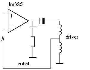
cheers
FF
 I'd rather not study patents, too boring.
The Neck Pickup Sweet Spot
in Electronics Chat
Posted
Have you thought about an explanation of the sweet spot in a more dynamic way?
An electromagnetic pickup causes a comb filter effect. The notches and peaks of the comb filter depend on where the pickup is positioned. At the sweet spot you've found there are 6 comb filters tuned to their respective open strings. Maybe you should compare it to tuning the carrier frequency of a ring modulator to the key you're playing in.
FF