


lovekraft
-
Posts
3,641 -
Joined
-
Last visited
Content Type
Profiles
News and Information
Tutorials
Product Reviews
Supplier Listings
Articles
Guitar Of The Month
Links and Resources
Forums
Gallery
Downloads
Posts posted by lovekraft
-
-
No, I suppose that a '59 Tele in good - excellent condition might be worth that price, but this one has at the very least had the neck pickup, the pickguard and the bridge replaced, and the electronics look suspiciously modern as well (can't really tell much from the photo, but I'm sure none of the '59s used a ceramic disc cap). '59s also had the infamous top-loaded bridge, while this body is drilled for a string-thru (although I suppose if it's a very late '59, that would be possible). In other words, the neck may be from a '59, but this guitar is no more a stock '59 than I am a Balinese diplomat! I guess that's what he forgot to put in the listing.

For reference, this is what a real '59 Tele looks like:
-
1959 Fender Telecaster Solid Body Guiitar - and only $10K!
The seller ended this listing early because of an error in the listing Yeah, you might say that!
-
Just out of curiosity, what simulation software are you guys using? I love my Circuitmaker Student 6.2, but it doesn't always tell the whole truth, and it occasionally gets so confused it simply gives up. Any better options (preferably for less than $1000)?
-
This is the most important question that's been asked in this whole thread, and it remains unanswered. Please describe the sound that you're trying to get rid of - without that info, this whole thread is useless, since we're all just speculating with no idea what the real problem is.When you say feedback, do you mean squealing, ear-piercing, microphone-held-up-to-speaker feedback, or do you mean buzzing or humming?
-
...why the in the world would I send my guitar to an expert (and pay them) for a guitar I built? In order to get it working properly! Nobody's bashing you, but it's obvious that you don't know enough to do this yourself, and apparently your friends aren't much help either, so it's time to involve a qualified tech. It's nothing to be embarassed about, but I've repaired enough guitars that were worked on by "...this guy my friend knows who really knows guitars..." to save you some time and heartache, if you're willing to listen. The odds of all three of your pickups spontaneously dying simultaneously have to be up there with winning the New York lottery, which leads me to suspect that either:
- Your pickups are not defective, or
- Your pickups were damaged in the process of the original "repairs"
- Your pickups are not defective, or
-
The Headwize Library -everything you ever wanted to know about homebrew headphone amps!
-
Why am I thinking this thread is a joke and I just don't get the punch line?
I almost missed it too, Joe - it was back a little ways:... I called my friend ... they said they had hardly any room to put the ground in (where the wiring schematic said to) so they grounded it in a different spot on the body ...
It appears to me that he has at least one (and perhaps several) fewer friends than he thinks he does.I had someone who actually "knew" guitars aside from just plain electronics. They went through the grounding process and realized my pickups were all jacked up... I suspect we haven't heard the last of this.
-
Using the diagram posted, turning down either volume pot is going to turn down both pickups (as in dual master volumes), just like a stock LP. If you're not going to use a switch, either reverse the pickup and jack leads on both volume pots (and move the tone cap to the wiper), or live with dual master volumes (and interactive tone controls). A blend pot would be the ideal solution here, but I have no idea where you'd find a 25K Orban-style panpot.
-
If they sound good, and they aren't noisy, they look pretty cool. I think I'd be more likely to mount 'em in a Hammond box with a footswitch, myself, but if you're looking for onboard electronics, these look pretty well thought out. It's all about how good they sound.
-
Curtis:
That's a nice little AGC circuit - it does, however, share the inherent problems of any JFET gain control circuit, ie, that both threshold and dynamic range will vary with the Idss and Vgsoff of the individual FET. Since the driver signal isn't part of the audio output (at least it isn't if we do things properly
 ), it probably won't matter much in this application. The feedback resistors around the FET will help linearize the response nicely, so you can probably adjust for device variance by trimming the FWR's gain - you'll simply have to try a few dozen FETs to be sure . Of course, using an optocoupler will give you more dynamic range, but since a little clipping apparently doesn't interfere with the driver signal's efficiency, it probably doesn't matter either. "Close enough" may be more than sufficient. In that spirit, you may find that a pair of 100K resistors will make a sufficiently "stiff" supply divider, and a JFET source follower could buffer the input, so you could use a dual opamp, further reducing current consumption - just a thought.
 Col:
I'm not sure we have to worry about the lower threshold, since the drive signal should never enter the audio output path, and noise shouldn't drive the strings at all, but it may be a concern. I'd love to play with this myself, but I'm in the final stages of "product development" for a stompbox that's supposed to be available first of the year, and prototyping isn't going swimmingly, so my time is spoken for, at least until I can get something I'm happy with working consistently. Besides, it would take me months to get a coil wound, and I expect you lot to have a working system by that time. If you'd like a couple of these VTL5C2s to play with/blow up/whatever, by all means, don't be shy (ask Pete - I fried 2 JRC386 chips back in the early stages of this thread
). As for simulating them, when I was designing my (unfinished) compressor, I just modelled the sidechain to generate enough current in a red LED to turn the LDR on without frying the LED (according to the vactrol specs - I targeted a max current of about 35mA, as I remember). The breadboarded "first draft" worked, but didn't sound as good as Johan's LA Light circuit, and I never got around to tweaking everything out, having other commitments at the time. Let me know.Pete:
Glad to hear things are improving, even if it's incrementally. Hang in there.
And finally,
Bancika
I cannot thank you enough for the layout software! It's really spectacular - keep up the good work!
-
IC1
- 0.76
- 0.76
- 0.71
- 0.00
- 4.75
- 4.80
- 5.01
- 9.55
There's part of your problem - the left opamp (pins 1, 2 & 3) isn't biased properly. Something is miswired - those three pins should be between 4 and 5 volts (like pins 5, 6, & 7). Make sure you havent wired something to ground (0V) that should be connected to Vr (4.5V). Did you ever get that spreadsheet converted to a JPEG? A look at your layout would sure be helpful!
- 0.76
-
The light/resistance characteristic of LDR's can vary quite a bit from piece to piece, which means that our DIY'ed compressors will probably vary in performance from one to another. They surely can't be any more varied than JFETs! Even the best made/most expensive JFET devices (Toshiba, Linear Technologies, et al) are all over the map, spec-wise, so they're gonna have to either be sorted for suitability (buy 1000, test 'em all, sell whatever won't work on Ebay) or trimmed in circuit somehow. A trimmer in parallel with an optocoupler's LDR should be sufficient for our purposes, and probably won't even be necessary if we use a production optocoupler like the Vactrol® or Siliconix Audiohm® devices. The only major problem with LED/LDR devices is the LDR has it's own attack/release characteristics, so you'll have to pick a model that's fast enough for your design. The good news is that LDRs are virtually distortion-free, have incredible headroom, and can be treated just like a standard resistor. Just my two cents - I think most FET compressors are prized for their non-linearities rather than their transparency, but that's just me.
More info here:
PerkinElmer VTL5C series Analog Optoisolators
I've got a few VTL5C2s that I can spare, if anybody wants to try one - might be a wee bit slow, but "close enough" for proof-of-concept work. PM me if interested. I'd give it a go myself, but there are already too many irons in the fire around here, at least for the next few months. A limited bandwidth (~60Hz-3KHz?) opamp "ideal rectifier" (with some gain) driving the opto looks to me like the simplest practical sidechain, but what do I know?
Y'all have at it - I'm looking forward to developments! -
Try disconnecting the wiper (middle) lug of P1 and tying that wire to ground, and see if the circuit works correctly that way ( I'll bet it doesn't, but what it does may point us toward the problem).
-
Honestly, I don't know much about the circuit in practice - I played one back when it was new-ish, and wasn't knocked out, but I'm not a noiztoyz kinda guy, so don't take my word for it. JD knows all 'bout it, though:
General Guitar Gadgets Green Ringer page
If you want real synth balanced modulator sounds, try googling "AD633 ring modulator" or "MC1495 ring modulator" - both Maestro and Oberheim made ring mod pedals using the MC1495, but they're both gonna be a bit involved to implement as onboard effects. Finally, the NE567 PLL chip has been twisted into a pseudo-ring mod, using just the onboard oscillator and the phase comparator.
-
If you simply use a standard 5-way and use a push-pull tone pot to add the neck pickup (to the output), you have the same possibilities, and you don't lose the tone control. Your diagram works, but it's "going 'round the end to get to the middle", and it looks very fiddly to use, especially on stage.
-
can someone help me out please?
OK, here goes:
- Guitar pickups aren't strong enough to drive a passive diode ring modulator.
- Even if they were, you'd still have to have a carrier oscillator (which would have to be powered), so it's still useless for your purposes.
Since you're just looking for "a bit of craziness", try a Green Ringer - it's a proven project, and a quick Google about should find you more info than you could ever have asked for.
- Guitar pickups aren't strong enough to drive a passive diode ring modulator.
-
If you can either post or PM me your layout, I'll take a look. You might want to take a look a this thread on debugging (from Aron's Stompbox forum) - gathering the info listed there will sure help anybody trying to fix it long distance .
-
IF you're looking for even a little clean, there's gotta be any number of better choices than a Super Distortion. As for what it'll sound like, alarmingly similar to the way it sounds in the bridge, but darker/muddier (you decide which - one man's poison, and all that) and somewhat hotter - not my idea of a good time, but to each his own.
-
Now whats going to happen If I end up useing Active pickups?
You're gonna be changing batteries between sets!
Worst case, you might have to add a trimmer pot to pad down the input to your pedal circuit. I doubt it'll be an issue with the DM, though. What are you gonna do about the dual outputs, use two jacks, or just 86 the Direct out? -
Ansil's right - unless you're looking for a huge boost, a decent buffer (like this one
http://www.projectguitar.com/uploads/emoticons/default_biggrin.png' alt=':D'> ) will improve clarity and presence without introducing any distortion or noise. If you want overdrive, the previously mentioned Stratoblaster or Don Tillman's FET guitar preamp are good choices, as is Jack Orman's AMZ MOSFET booster. Opamp boosts are also easy, but often require a few more parts, and can be noisy if poorly designed.
Keep in mind that even with the best circuit, more than 20dB of boost is probably going to exceed the headroom of a 9 volt powered circuit and generate clipping distortion (not necessarily a bad thing, if that's what you want).
-
Adjust the trimpot until you measure 4.5 - 5.0 volts from the drain of the FET to ground - this is to compensate for the huge variations in devices, an unfortunate by-product of the manufacturing process. The Fetzer Valve page has an in-depth explanation of this.
-
For a simlar idea (complete with component values), with a lot of extra tech info, check out Jack Orman's Guitar Pickup Simulation article in the AMZ Lab Notebook.
-
This thread needs a full-time historian/anthologizer!
Seriously, I've been "away" for a while, and just recently got my computer back up to full working status, so I've missed and/or skimmed through a lot of the recent developments. Anybody up for a semi-current "State of the Project" report, so we can avoid tripping down the same blind alleys we were exploring back in 2004? Apparently most of the recent work has been in driver design - can somebody do a basic comparison of the current ideas, contrasting the pros and cons of each design? I'd be ever so grateful!! If we can catalog what has ( and more importantly, what hasn't) worked in the past, we might narrow things down a bit, and not waste time pursuing approaches that have been proven repeatedly unsuccessful. Just my two cents - now I've got some in-depth reading to do.
-
I've always been partial to the Ibanez JEM setup - it's a nice mix of dual hum sounds with a couple of strat-ish in-betweeners thrown in. See Jemsite's Tech Page for several switch options (scroll down to Wiring Diagrams).

 ), it probably won't matter much in this application. The feedback resistors around the FET will help linearize the response nicely, so you can probably adjust for device variance by trimming the FWR's gain - you'll simply have to try a few dozen FETs to be sure
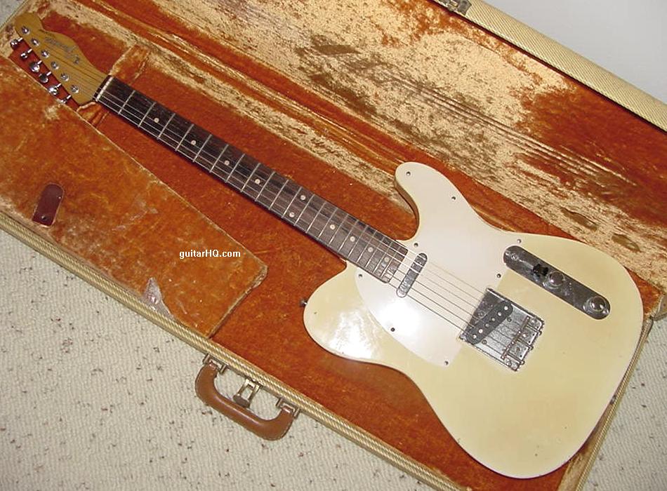
Versatile Pu/wiring Ideas
in Electronics Chat
Posted
Well that's easy enough - warm DeArmond-ish jazz humbucker in the neck, clean vintage Strat pickup in the middle, and screaming humbucker in the bridge. Dual coil splits and standard 5-way switching should give you plenty of options. As for an acoustic sound without piezos, buy an acoustic simulator pedal. Of course, it's not going to really sound like a Strat unless it's a bolt-on with a trem, just like it's not going to do the LP/PRS thing perfectly unless it's a set-neck with a fixed bridge, but you might get close enough.