


bancika
-
Posts
99 -
Joined
-
Last visited
-
Days Won
1
Content Type
Profiles
News and Information
Tutorials
Product Reviews
Supplier Listings
Articles
Guitar Of The Month
Links and Resources
Forums
Gallery
Downloads
Posts posted by bancika
-
-
Is this another single coil driver or some other design. One problem with winding on the magnet is that you are stuck with those dimensions for the core. Another, is that you will have to destroy the device to recycle the magnet. With a blade design the magnet can be used as often as you like for other ideas and you can vary the core material and size.
There are advantages to an internal magnetic core though...possibly faster, different field characteristics...but, the main thing is you can make it more compact...
I'm thinking about stacked coil design. I'll try to find some blade material and try to do it with separate blade magnet, then. It sounds more flexible.
It is a long hard road...and it seems to be getting rockier.... pete
Sorry to hear that, hope everything will be ok
-
Here's more info:
as seen on photo, driver is wounded on old strat pickup bobbin with core about 60x6mm with magnetized rods as pole pieces (I assume they are AlNiCo V). Before I connected amp to driver I tested it with speaker to make sure everything is working OK. Wire is 0.20mm Pete sent me, which is the same as he used, so I ruled that out. I measured about 8.2ohm of DC resistance of coil, which should be fine. I'm still trying it with power supply, so it might be the reason.
As for 2nd shot, do you suggest trying to wind around blade and put magnet under or just wind directly to magnet. I have magnets suitable for both designs, one has 5x6mm profile and one is about 5x12mm.
I hope everything's OK Pete!
Best regards
-
Hello,
I finally made a few clips of my sustainer during hand test. I recorded from guitar to preamp and then to PC sound card.
I'm really not so sure which mode is which any more. The one I expected to sustain more actually gives me harmonics and "clean" one sustains much less with same settings. IIRC settings are Gain 0%, volume 60%.
Also, problem with G string remains the same. No matter which string I hit G has most chance of vibrating (followed by low E). Also, harmonic mode (which sustains more) increases vibration all time, some kind of AGC would surely help there. If I reduce ruby volume that effect decreases but then other mode is even more subtle.
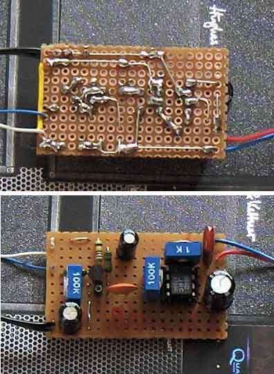
By the way, here's a photo of my Fetzer/Ruby that drives sustainer.
I'll make bobbin for that piece of magnet I have and try dual coil blade design to try both.
One more thing, I've found another magner rod but it's broken, so it's only 52mm long. I checked with my guitar and at 24th fret it's only about 1-2mm wider than string spacing. Does it make any difference if I use that one instead of 60mm long one?
Cheers,
Bancika
-
Hello,
can someone tell me how to determine magnet polarization, how should I place when winding coil. I'll do one driver wound directly to magnet I have, it's 5x6x60mm which should be good.
-
It's easy when you have back access panel. On strat style guitars it's PITA to remove strings, pickguard etc. On floyd rose equiped guitars it's even bigger mess

-
I've been also thinking about offboard sustainer, but I doubt that one could make it with single cable. Sustainer level is much greater than guitar level, there will be nose, squeal and whatnot. One solution could be using two cables, but then it's ugly. It would be cool enough to have external power supply. I wish I didn't cut my stereo cable into smaller patch cables
Even having batter outside is a success. Using short stereo jumper cable and small battery box attached to guitar strap (like wireless system). Jumper would go from guitar jack to strap box (it goes above strap anyway so it won't be visible). It's the same thing just you don't need long stereo cable. On the other hand you need lots of batteries, so in the long run it's better to go with floor based unit
Cheers
-
well, yes, I used wall wart power supply. It isn't regulated but has a 2200uF filter cap IIRC.
I'll try to put it into preamp and then PC later, thanks!
Just split the signal out of the guitar to two jacks one in and the other to go out at the input of the sustainer circuit...so it goes to the sustainer and to the soundcard. That's how my "sustain box" was wired.
yeah, that's how I did it...
Branislav
-
I plugged it directly into mic in of my sound card. What I did is take output of guitar (after tone and volume controls, bridge pickup is selected), split it it two, take one to sustainer and other to PC. Nothing is connected between
-
Hi,
few questions: how should I wire sustainer at all?
I tried to make a sound clip of hand test but have a problem. When I wired it in parallel with guitar output on my last test signal didn't even come to sustainer circuit. Only when I unplug guitar cable I get signal coming to sustainer. Weird?!
Second, I noticed that when I hit high E string (jn sustain mode) it doesn't sustain but instead G string vibrates in that pitch. I didn't notice that last night. It will maybe be different when I install driver but it's weird anyway.
What about phantom powering sustainer circuit using stereo guitar cable. One "stompbox" would be connected to 9V power supply as all other pedals and send those 9V through second "channel" of stereo cord. That would eliminate battery nside guitar.
Cheers
-
tnx guys. I hope pics and clips will be ready soon
next up is new driver with that magnet I have with stacked coil. I'd like to compare them before installing.
One question.If I wind both coils in the same direction I should connect both starting leads (or both ending) together to get humbucking mode?
should I just solder then together on bobbin without making wire taps?
Cheers
-
RESULT
I finally finished soldering amp. First I tested it with speakers to make sure it's working OK and I've got little confused. When I set bias for JFET to anything above 3.5V it hums like hell and guitar sounds like it has some kind of ring modulator/octaver effect. At ~3.5V there isn't hum but still a bit of octaver thingy. Reducing drain voltage to ~2.2V solves it. I tried another JFEt and it was the same. Anyone with the same expirience?
Then I hooked up driver and tried holding it in hand above strings at about 24th fret (that's where it will be on squier) on my main axe (non-suspecting squier isn't around). Little messing with trimmers (gain and volume) I got some kind of result! Because I used guitar cable to connect to fetzer/ruby I couldn't plug it to amp and hear what it sounds like there but "dry" test went pretty well. Both modes work fine. Even high E string vibrates infinitely.
How do you guys set gain and volume? I set mine to 50% gain and 100% volume. It's just a test, when I install it probably it will be somewhat different.
One more weird thing: when I press my ear to driver I can hear it humming. When neck pickup is active it also wistles in high pitch. Maybe it's because it's near neck humbucker?
Cheers and thanks for great project
-
I just got back from the store getting all remaining parts for amp circuit. Hopefully I'll have some kind of result tonight
Cheers
-
Yes, those large ones come from two coils of humbucker (the cheap one) and smaller ones are also from other humbucker, just magnet on one coil was missing. I'll ask a friend who gave me pickups if he still has it, if he has you can have it
I'll have to make a bobbin (have nice sheet of 1mm plastic that I got by mistake for pickguards, it cuts really well)..and I'll probably try stacked design. It can be only better, right?
-
No, it's 10mm high and 5mm wide. I'm not sure wat are you reffering to with "width"
It's thinner than tim's core, but taller. I have one core that's about 5x5x60mm (from one of pickups I got), which is very close to tim's just a bit smaller. Maybe it's a better choice.
Cheers
-
What about winding directly to magnet. Those magnets salvaged from pickups are approx 60x10x5 mm, can I just use them as a core. I'd like to build one blade prototype and do side-by-side comparison with discrete driver on same amp circuit.
-
yeah, it's just acting like master volume. It's stupid to give 20$ for one pot in a box. L-Pad attenuator is much better choice and it costs about the same. It goes after speaker so it won't reduce power amp distortion. At really low volumes it can suck a bit of treble but putting 2.2uF non-polarized caps across it will fix the problem. You can also build fixed switchable L-Pad with only two resistors for fixed attenuation you choose.
-
one more thing about "concentric coil design" what about making inner coil much larger than the outer coil. It would have enough power to drive strings and outer coil would keep EMI down. In my case, for instance, it would be 100 turns inside and 12 outside.
-
That looks great, very well made, I knew that wire was going to a good home!

Some ideas are so good that you wish they would work from will alone
...however... One of the interesting things about this project is that it makes you think about things that we tend to take for granted in our everyday world...like the subtlties of electromagnetism.So...a coil of wire will make an electromagnet when a current passes through it...actually a straight wire will, it is the overlapping wires that build upon one another that factors into the strength of the field. Hence, I found that the thin coil is ideal in that you get a good number of overlapping wires...winding the full bobbin with the same amount of wires will not produce the same effect.
Hi,
did you reffer to my coil? It's not winded all way, just 3-4mm
Cheers
-
Hi guys, I'm back.
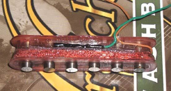
Finally got a camera to take a few pics of progress.
I finished winding my first driver, coil is potted with transparent glue. Leads are also glued to bobbin.
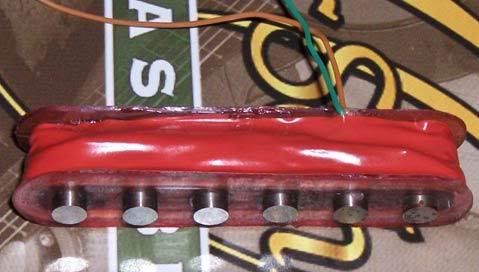
And a photo after it's covered with insulating tape
You can see here that I set pole pieces for lower three strings a bit higher. After I test it I'll re-align them if needed.
What do you think about it so far?
One idea for dual coil design. What about taking two winding wires together and wind them together. After winding enough (half of turns needed for usual one wire winding) just solder oposite sides of coil together. Maybe someone suggested it before
Cheers and thanks for help.
-
Hi,
I just wanted to pop in and say that my driver is mostly completed. I just finished winding. I potted coil with glue, soldered leads and glued them to bobbin. It looks decent, considering it's my very first attempt.
Also I'd like to thank Pete for sending me a spool of winding wire
As soon as I find a camera to borrow I'll take a few photos. I'm making a photo essay for those even more noob than me
Will keep you posted...
Cheers!
-
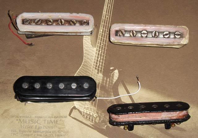
Those pickups on top are two coils of a broken humbucker
Anyway, one of pickups (bottom left) should be working and I'd like to try it on my squier. It should be diMarzio or Schaller, better than stock anyway. But the thing is those leads are very thin and flimsy. Any ideas how to connect "normal" wire to coil in case these POS leads isn't good. I know it's a bit off topic, but you guys are expirienced with this
Cheers
-
Hi,
Pete, I've received your mail but couldn't reply because your mailbox is full. HUUGE THANKS
By the way, a friend gave me a bunch of old pickups to experiment with...here's a pic
Cheers
-
Got back from search and nothing. Anyone knows where can I order it online. Most shops do not want to ship to Serbia.
Anyone wants to sell/trade wire sufficient for 2-3 drivers?
Cheers
-
yeah, I was asking for 0.2mm copper wire used for coils/transformers/windings...they seemed like they hear about it for the first time in life


Sustainer Ideas
in Electronics Chat
Posted · Edited by bancika
Hi!
Today I've made a blade for my 2nd driver out of large 3mm ferrite sheet I found in the basement. It turned out really nice, I coated it with black acrylic paint after sanding it, but it just occured to me now that 3mm thick blade maybe isn't enough? What do you think, should I use this or make another one out of 5mm sheet I have?
Also, do I need to make top radius on my blade to match string radius?
My plan is to make bobbin out of thin 0.8mm plastic and cut it with laser to make everything look nice. Also, I got black plastic pickup cover to put driver in.
Tnx