


Grimzors
-
Posts
73 -
Joined
-
Last visited
Content Type
Profiles
News and Information
Tutorials
Product Reviews
Supplier Listings
Articles
Guitar Of The Month
Links and Resources
Forums
Gallery
Downloads
Posts posted by Grimzors
-
-
Not that i can help you with your problem, electronically inept, but i used the Wizard and was given the same schematic (10 led's with 5 resistors) and after a bit of headscratching (i'm using 2mm leds for side dots and they're not marked which side are + and which are -) it's been sitting wired up fine on the bench for 3'ish weeks and still has plenty of life in the battery so it could perhaps be the switch as PSW says. FYI i 'm using a standard DPDT switch like you'd use as a coil cut or the like, just connected to two of the six terminals.
hmmm, well im using 1 resistor per LED, not 1 per 2, because the wizard said 2x5, even though im horrible at math i know thats 10..hah
-
LED= Light Emitting Diode.
The resistors on the LEDs are for current limiting.
If you connect an LED directly to a 9V battery, it will blow immediately. I think those resistors are a little small, IMO. I would have made them bigger to knock down the current a little bit more. Like maybe 1K or so.
Anyway, if the switch was wired properly, it should be impossible for the battery to get drained as it physically breaks the connection. Something has to be defeating the switch somehow...
good point, at first though i did try bigger resistors and it would heat up the batter in about 5 seconds to where you couldnt touch it...anyways i cant change them out now theyre already in the neck....but there has to be something with the switch
-
theyre wired parallel, i'll try to draw it up tomorrow
Solution 0: 2 x 5 array uses 10 LEDs exactly
+9V
+ -|>|- -|>|- -/\/\/\- + R = 150 ohms
+ -|>|- -|>|- -/\/\/\- + R = 150 ohms
+ -|>|- -|>|- -/\/\/\- + R = 150 ohms
+ -|>|- -|>|- -/\/\/\- + R = 150 ohms
+ -|>|- -|>|- -/\/\/\- + R = 150 ohms
The wizard says: In solution 0:
* each 150 ohm resistor dissipates 60 mW
* the wizard thinks 1/4W resistors are fine for your application Help
* together, all resistors dissipate 300 mW
* together, the diodes dissipate 660 mW
* total power dissipated by the array is 960 mW
* the array draws current of 100 mA from the source.
-
-
Oh and also, when i turn them on...sometimes it takes a few seconds for the lights to actually turn on...
-
sorry guys was away from the pc for a day...well if anyone can find the LED wizard, i wired it exactly how that told me to, using the same resistors, i know the LED wizard is on here somewhere but i cant find it, maybe someone with better searching skills can? and yes the LED's are all wired correctly i believe, like i said the battery doesnt heat up, and when i turn them on the battery doesnt die within 5 minutes, its when its off that it drains, my only guess is that some wiring must be wrong on the switch part...let me try to describe how its rigged, so there's 10 led's in the circuit, the wizard told me to use a resistor for each one, and i forgot the resistance nnumber of the resistor but its a small one, anyways, its all wired correctly positive and negatives, now when it gets down to the switch and battery adaptor the positive wire and the positive wire of the battery are rigged up to one side of the switch while the negatives to the other.
there is some good news though, i strung the guitar today and it plays fine
 no weird fret buzzing or anything
 -
OK...thanks...
If the battery is not overheating (good point) and you are disconnecting it at the switch, then it may well be that is all you will get from the battery. If it is not connected, then there can not be drain while not in use as far as I can tell (without knowing what you have done). Remember, even though they are only a low voltage, lights still draw a fair amount of current and a whole string of them even more. If you up the value of the "pull down" resistor you may get a dimmer light that lasts longer.
good luck...pete
hmmm do you think there is some type of wiring i can rig so it can run off the input jack power? i really need to tackle this issue!!
-
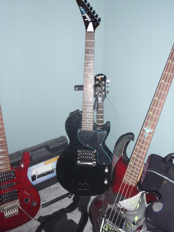
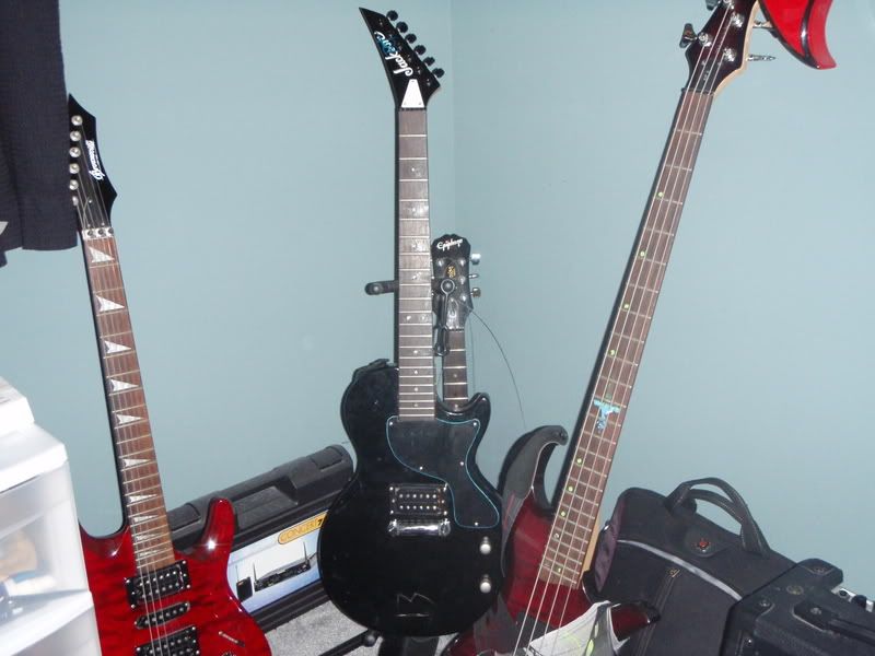
there is no real picture i can get of the wiring diagram, thats a picture of the guitar, there was a post somewhere in here before with the diagram but i cant find it
-
Well, its wired as it should be, resistors, LED's everything i just really cant think of why it drains while its off, i used an LED wiring wizard and everything, and the battery doesnt over heat.
id assume the neck just has to be set or something, i'll take it to my local luthier as soon as i can
-
Anyone???
someone in here has to have one they dont use....i'd be putting it to good use recording and making music...
-
so recently i setup a neck with LED's in it, first guitar project ever done, and but the jackson reverse neck onto a epiphone les paul body...looks mighty sick...anyways the battery gets drained even while the lights are not switched on, any ideas?
and also the neck looks like its sticking up a bit out of the inner part of the pocket, is that normal?
-
Hello there, im looking for a roland g 707 or a g 77b, main influence to get this guitar is amir derakh , and just because its a badass guitar, and the bass version is sick as well!
anyways im ready to buy notify my at grimzors@hotmail.com if you got any info or are selling!
-
Hmm there's no mockingbirds there :-/
-
guitarbuild.com and go to the free downloads
thanks a bunch!
-
Well im trying to put a guitar together here, does anyone know where i can get a mockingbird Pdf. file, or where i can possibly buy a cheap mockingbird blank?
-
alrighty i will try my best to take care of that, next time ill use the flat LED's or the 1mm ones :-/
-
PITA? lol, well its only about 2-3 that stick out majorly, and the otherones are barely out at all, its not even liek a mm, so idk ill test it on a regular one out of the board and see how far i can go..
-
Yea, ill remember that next time, ill try sanding an LED thats not in my board first off to see what my limits are
-
is it possible to sand off an led a bit? some of the are popping out a bit of the fret holes, what can i do? also what should i fillt the hole with? clear epoxy? thanks
-
wow...i cant believe it me and him just talked a few weeks ago, he helped me out alot, i dont have much to say about him i didnt know him all the long but im sure he was a great guy from what ive read here, and he will be missed
-
Eh well maybe next time, and yea im planning on finishing the re attachment i think thats when i will post it up, just because i ran into some snags doesnt mean it came out wrong, ofcourse ill write down things i didnt do in advance etc, but thats for your help
-
Yea thats smart but its too late! lol the battery is fine hasnt heated up only thing i am worried about now is the LED sticking out of the frethole, could i sand it down a bit? and i think im probably going to fill the hole with clear epoxy or something, i saw someone say that
but yea also i hope it all fits down well, i asked my uncle for a dremmel so hopefully ill get one soon, here is a little demo pic of whats going to be in the tutorial http://i20.photobucket.com/albums/b237/Gri.../Picture177.jpg -
Oh well, we are using the 100 ohm 1/4 watt already...i dont think ill be going back to chance the resistors...>_> we are already done with 4 LED's everything is going good the battery heats up, but i guess thats normal, the snag we are onto now is how to do the 12 fret marker with the 2 dots...lol ill keep you guys informed and remember to send me any info, as i will be making a tutorial, ive been taking pics here and there and have a few diagrams, i will give credit to those who contribute, thanks
-
Description
Emitted Color : Blue
Size (mm) : 3mm
Lens Color : Water Clear
Peak Wave Length (nm) : 460 ~ 470
Forward Voltage (V) : 3.2 ~ 3.6
Reverse Current (uA) : <= 30
Luminous Intensity Typ Iv (mcd) : 4000(Typical) ~ 5000(Max)
Life Rating : 100,000 Hours
Viewing Angle : 20 Degree
Absolute Maximum Ratings ( Ta = 25°C )
Max Power Dissipation : 80 mw
Max Continuous Forward Current : 30 mA
Max Peak Forward Current : 75 mA
Reverse Voltage : 5 ~ 6 V
Lead Soldering Temperature : 240°C ( < 5 Sec )
Operating Temperature Range : -25°C ~ +85°C
Preservative Temperature Range : -30°C ~ +100°C
Quantity : 100
Free Resistors (Work for 12v)
is that better? lol
 and see if anything happens
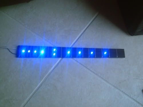
Battery Drains Too Quickly...
in Electronics Chat
Posted
well it doesnt heat up now, months ago when i was experimenting it would. it has to be something with the switch...