


mistermikev
-
Posts
4,759 -
Joined
-
Last visited
-
Days Won
133
Content Type
Profiles
News and Information
Tutorials
Product Reviews
Supplier Listings
Articles
Guitar Of The Month
Links and Resources
Forums
Gallery
Downloads
Posts posted by mistermikev
-
-
17 hours ago, Crusader said:
Keeping track of how long things take is one reason why I take so many photos. I never tally things up but its there if I want to later on
I used to take a lot more photos... but cnc has made the way I work so useless to others it seems. very specific to me and probably boring because a lot of the interesting stuff happens at the design part... and mostly in my head... and taking photos of myself at the pc would just be silly!
-
 1
1
-
-
48 minutes ago, ScottR said:
The piles of chips I've swept up are way bigger than the chunks of wood they started from. I suppose one could say I took one big wood chip and subdivided it into many smaller chips.....
I have no flippin' clue! I honestly don't even see it when I'm working on it. But then I see it in the pictures and wonder where the hell did that come from? I presume that ash board was once on a pallet of similar ash boards, and had something stenciled on the stack. So those might not even be complete letters. And later there will be wood chips with parts of that stenciled on them.
Or maybe that board moonlighted as a giant scrabble tile in its past.
SR
"tooty" seems much more plausible lol! that board belonged to the infamous tooty!

-
1
-
-
crazy to look at that origin and think about how many individual cuts it has taken to get to where it is.
also... find myself wondering... what is significance of "II T"... hmm and interesting riddle. perhaps you are a big fan of "the facts of life"? a reference to terminator 2? the possibilities are endless...
-
 1
1
-
-
17 minutes ago, MiKro said:
Been using steel pins for years Mike. I have 1/4" mainly. you just have to make sure they are not in the way of any cuts as a router bit will suffer big time if it hits it. If an end mill hits it it may or may not do well depending on DOC, end mill type , etc. LOL.
It is good info to know though.
MK
hehe, funny you mention that. I had great concerns about hitting them while moving my machine around manually... perhaps forgetting and wham! Having lived throught the "put a 1/4 endmill through my aluminum truss rod event of 2022"... I don't want to be anywhere near if/when that sort of thing happens. the funny thing is... the whiteside bit I did that with - totally fine. That is the one I just cleaned and am still using for everything. Aircraft grade aluminum - cut that truss in half like nothing!
I actually use nylon nuts/bolts and T-slots in my spoil board to hold my stuff down, so I just use the pins to get into position and then tighten down my bolts and remove the pins... but thank you for the thought! not sure my whiteside would fair as well against steel!

-
1
-
-
5 hours ago, curtisa said:
Good to know
 . Yes - I was aware of premade locating pins for this kind of thing.
My original idea of using bits as locating pins was to use old, broken ones and insert them backwards (ie, shank down). As a fellow amateur computerised wood dust generator, like me you've probably destroyed plenty of bits on your way to learning the ropes on the machine. A 1/8" shank bit in a 1/8" hole has no wobble, and it doesn't mater that the bit is broken - you can be as rough as you like putting them in or out of the holes if the cutting edges are already no good.
hehe computerised wood dust generator lols.
I was not aware that you could buy locating pins... I guess forrest for the trees.
I have yet to break anything above 1/8" bits (have def ruined a number of .0236 bits!)... and was going with 1/4" bcuz the 1/8" bits I have would be entirely too short to make it through the necc 1 1/2" and have enough sticking out that I could grab. the other concern was... the bits were going in tight enough that getting them out by the blade was going to result in a cut finger sooner or later. I guess if I had some old ones I wouldn't be concerned about pulling them back out with a pliers tho.
I probably should have some old ones by now but cleaned up my one 'older' whiteside the other day with some saw blade cleaner and it doesn't tear out at all even on hard woods so... she's got plenty of life yet.
Either way these will be great cause I can mark them at depth easily and pretty cheap. 2" long so plenty sticking out to grab.
-
so... recently read and re-read @curtisa's thread about tiling a fretboard with cnc. (thanks for that!) Full disclosure - also got a lot of help from @MiKro. Well I did the tiling and I don't have anything precision to measure out quite that far but via tape measure it looks good. smashing.
so... as curtisa suggested I used my cnc bits as the pins to locate the piece... and while this is a great idea... I felt like I wanted to use the butt end of them because there would be less chance of wobble... and that means pulling them back out with my fingers and risking a cut... or pulling them with a pliers and risking damaging the knifes. Further, my shorter 1/4 bits are really only 1.75" total... and going through 1/4 fretboard + 3/4" slide board + 1/4" depth of cut for location hole... doesn't leave much. I also wanted to scratch/mark them so I can be sure of the depth - but not doing that on my bits...
so with that in mind I figured I'd take a chance on the precision of the steel locating pins I could buy off amazon.
well... bought them and checked them against the holes I cut with my whiteside bit and they are perfect... just wanted to pass on in case anyone else can benefit - link below. $13.49 for 10 pins and money well spent.
https://www.amazon.com/dp/B086DCHYQK?psc=1&ref=ppx_yo2ov_dt_b_product_details
-
2
-
-
first would like to suggest you go get the free diylayout creator... as it's a lot more organized.
your blade switches - it's impossible for me to know how they work and which lug is the common looking at them... but I can tell you just looking at it that you've got the live connected from one single to the live of the other and then to several lugs... at least that's what it looks like... so those two coils would just be connected together and always on (probably not what you intended).
if those blade switches are supposed to be slide switches... then perhaps get a picture of the back side of one and you can import that into diylayout creator for a more clear documentation of what you intend.
looks like either a diode in parallel with a cap... in series with a resistor... or perhaps it's an op amp with a cap in the feedback loop... hard to tell. if you put a .15u cap and diode in parallel that is likely going to allow everything over say 100Hz to clip... and then that is ltd by the resistor. you are basically creating a passive overdrive similar to the 'black ice' that was popular a while back.
not sure what the point of having a cap on either side of the resistor is there... no idea what we're trying to accomplish there but in theory when that is switched in it would cut bass and resist the diode more?
also... you might as well describe what you thought this circuit would do.
anywho... that's about all the guessing I have in me for now.
-
it's not so much the face... but the look on the face...it's mocking me even now! hehe was just a joke... it would be a mistake to ever take me seriously hehe.
-
1
-
-
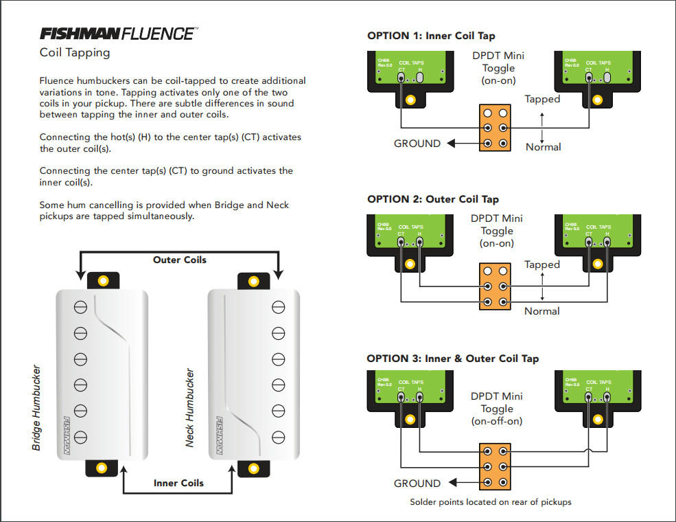
20 minutes ago, Prostheta said:
The design is relatively vertical in terms of it not being that modifiable. Each pickups seems baked into the three modes with accessory options like the frequency tilt and volume reduction. In principle you are correct, however I'm not sure if the design would allow that even if the internals were accessible. I noticed a few plated through holes on the bottom, however it would be unlikely that tapping into any of these would be easy or productive. Not as ripe as you might think by unit, however the platform itself might lend itself to some pretty odd options and possibilities. Or completely not.
i guess it would boil down to whether or not they decided to do that or not. in theory... you could have a through board eyelet that you just avoid once you get over 80% of the coil. that'd be an 80% tap... but I have no idea what the wires are actually hooked up to... and in theory somewhere in that stack of pcb there could be an smd resistor for a partial tap... or any number of other things. will have to read more on the site and see if they divulge this top secret info!!
looking at below... def seems to be some sort of either coil tap or just splitting on the first two wires...

sorry for blowing up your thread with diagrams... but i hope it's ok given you might directly benefit? here's another one showing how to coil tap anyway...
-
1 hour ago, Prostheta said:
It'll be a very different neck tone for me as well since I normally play 22 frets rather than 24. I'm interested to see how the Fluence neck pickup works with the tone dialled all the way back. I have some work to do to figure out exactly how I want the blade switch to operate, but likely I will need to become familiar with the tones on tap from the two voices. I imagine something like PAF (voice 1) either end of the blade (1+5), voice 2 (hot rod, chime) either side of those (2+4) and maybe something else in the middle such as both pickups in voice 1 (PAF).
i haven't studied the fluence and what they are doing with their different 'voices'... have not found a resource that explains exactly what they are doing but given the idea of a multi layered pcb in lieu of actual wires I would think it would be foolish not to take advantage of the idea of tapping the pickups 80% of the way through the coil and doing an overwind as it would give the option to do a classic paf wind and then switch to an overwind depending on wiring... but haven't seen any literature that explains what is actually happening. that said... if they ARE doing that... this would be a RIPE situation for doing a mismatch of coils. ie 100% neck wind on one coil mixed with 80% bridge wind on opposing coil. if you/anyone knows... would love to read that.
-
2 hours ago, Prostheta said:
Last post, February?! Wow, I really have let things slide. So sorry everybody....employment is being a PITA (more accurately the lack of it) so my focus has been elsewhere. I'm scraping together the expensive bit for any guitar - hardware - and getting paint done when I can find some good time to do it.
Quick question that I'd like some input on. The white Mirage is going to get Fluence Classics, however I've torn between the open core or the covered (gold).
Old render (hence silver fretwork) with an approximation of Fluence Open Core pickups (but not with gold poles):
Up-to-date render with covered Fluence Classics:

gold covers with gold evo frets... that is a ladykiller right there imo. fluence is so on my list of things to try at some point. such a cool idea how they are made. I really like their design for metal covers too. looking fwd to it!
-
2 hours ago, curtisa said:
Then the narrowest spacing between any two traces you can achieve is .o177". You'd have to check if that would be acceptable for things like DIP packages, where the pads sit on 0.1" centres.
Might work? I never had much success with my usual doublesided tape method in the past; if the board was warped it tended to have enough spring to pull itself off the bed partway through the job, which would naturally ruin the PCB. Haven't tried the tape/CA method though.
It's hard on the tools. Typically you'd use solid carbide bits which will go the distance in fibreglass but they're more brittle than HSS or steel alloys, so they can break easily.
A straight bit will avoid the issue with the PCB artwork growing/shrinking if the board is warped, but they will snap as soon as you look at them if they're asked to go through a high spot in a warped board. That's why most people recommend a vee bit with a shallow tip angle for PCB work. They're much more forgiving to unexpected changes in cutting depth and you can move them faster in the material.
dip... well just tested by adding a .0177 circle to my diylayout creator and moved it around the board... yes good call the dip is where it is going to be the most problematic but should work ok.
tape/ca - well perhaps I'll have to set my level for each 2" x 2" section to mitigate.
that said... I could simply zero a hair above the board, and cut deeper... forcing the bit to cut a bit of 'air' before cutting the pcb. it's gonna take that much longer but would mitigate potential issues of cutting too deep and breaking a bit. the end mills I use are carbide but I imagine at the least it's going to dull them up pretty fast.
with all this in mind I think I might do a clearing pass with a .0625 bit and then just use the .0177 bit to clean up the really tight spots. this is all good info and is going to give me a lot better chance at success so - thank you very much for the help!!
-
27 minutes ago, curtisa said:
I've done it a few times, but it's a fair bit of hassle to get it to work right. Unless there's a very specific reason why I need to get a one-off PCB made up I normally just get them done by one of the online Chinese PCB vendors like JLCPCB or PCBWay. It might cost more and you end up with multiple boards if you really only wanted one or two, but it takes away all the heartache and stress of trying to do it all yourself.
But if you're interested...
For really small boards without much detail it can work OK without all the height probing. I've done a couple of pedal-sized boards like this that came out workable in the end, although not perfect. They were double-sided designs so the result was far better than I could have managed using things like Press 'N Peel or photo resist. The problem is that if the blank PCB isn't perfectly flat (and they never are) the routed traces will grow and shrink as the lumps and bumps in workpiece drift closer to or further away from the bit. To combat this try and limit yourself to small designs with generous trace widths so if the routing does get affected by a slightly warped PCB there's still be enough of the circuit left to work with. You may also be able to devise some kind of clamping system that squeezes the four edges of the board tight against your CNC bed which could help reducing any warp in the PCB.
For anything bigger than a couple of square inches, you really have no choice but to use height probing and surface mapping. The warp will be too great and you'll risk the artwork fading out completely in the low spots, the PCB traces shrink down to nothing in the high spots, or the tips of the bits get broken if they're pushed through too much high material. Again, I've done it but it's still been a bit hit and miss. Maybe if I did it regularly I'd get more consistent results, but it's such an infrequent thing for me I find I have to relearn everything pretty much from scratch, which invariably results in broken bits or a board that is unusable.
The software I've used to do the probing and surface mapping is AutoLeveller, and the PCB artwork I generate using FlatCAM. Both are free. When they work they do work well, but getting them to work in the first place can be a bit of struggle.
Note that if you do decide to explore this idea a height probe/tool setter is still an extremely useful addition to your CNC. I added one to mine a few years back and even without doing much PCB work it makes multiple tool changes within a single job soooooooo much easier. You can get away with touching off only once at the start of the job and then just wait as each stage completes to install the next tool, It does the rest automatically without losing tool height, even if the tool length is different each time. Beforehand I was having to split the job into multiple files, one for each tool, and touch off at the start of every file.
awesome info... I am very grateful. yes... unfortunately everything I do is a a 1-3 off. I usually do up a board of 3-5 designs at one time... but I'm always trying new designs or improving/changing my old ones... so a pcb fab house is a nice fallback... but I'd rather at least pursue this route.
for me this would only be single sided so that keeps it a little bit simple. I haven't checked yet... but was planning on using my .0177 bits to cut. idk if that will be small enough... and I know it will take forever... but I have success with those for wood so hoping that level of detail would be ok... or I'll have to start re-designing my stuff.
perfectly flat... well... my plan was to use a perfectly flattened piece of baltic birch and use the tape/crazy glue method to secure. I was thinking I'd mill a whole 6" x 8" pcb board... but perhaps that's crazy talk. is fiberglass really that hard to cut?
also... I'm not planning on using a tapered bit... but a straight shank .0177 bit. I figure this way... all I have to worry about is getting low enough to cut the copper completely.
I cut .06 depth with the .0177 bits through ebony w/o issue... so I guess I'll just have to find out how hard fiberglass is by compare.
touch probe... that does sound nice. I know I should def get one. currently I just pick a zero spot and mark it... and I'm really good at driving a bit right up to the wood fairly fast. I've figured out the quick keys to help me move rapid to the spot and then once I'm within 1/16" of the zero point I just use the slow keys while watching carefully... really doesn't seem like too much of an inconvenience but I will keep your words in mind.
thank you very much for the input... I will reread and digest!
-
I have read on the subject quite a bit and am aware of folks who use some sort of touch probe and software to create a map of a specific circuit board and then the cnc code is modified for height when machining... I'd like to forego this alltogether.
I can't help but think I'm missing something, but I use 2oz copper pcb and 1/8" thick fiberglass backing so have lots of height to spare and it just seems like it would be easier to cnc it like any other thing I might cut. Just wondering if I'm missing anything? I plan to do this in the near future as I'm tired of manually making pcb so as soon as I run out of etchant I'm switching over.
any/all input appreciated.
-
7 hours ago, komodo said:
LOL. It looks like Gary Bucy.
hehe, does a bit.
-
thats-a one a-spicy meat-a-ball. I love the guitar, nice top, clean work.
that said I honestly wish I could stop seeing your avatar... i'm gonna level w you... it makes me think you are a not nice person... I'm not even sure why... cause you seem like a nice person. it might be about me... r u making fun of me w your avatar? hehe "I will not be mocked"
-
12 minutes ago, MiKro said:
So Mike, if this is a fretless Bass why the fret slots? I did not read the previous if it was stated there for whatever reason?
MK
well, I never mentioned either. good observation. the slots on this one - my prototype, are actually going to get frets... but on the other one I'm going to do the sm slots in a purpleheart board and then put maple veneer in them. also the "profile" there will get veneer on both. I can't play fretless without training wheels!
-
1
-
-
well... with @curtisa and @MiKro on my shoulders... I completed my prototype fretboard over the weekend... learned a few things too.
as it were... I found the built in logic to tile my fretboard was not going to work for me. the logic is expecting one to move the length of the tile... and if you set a really large overlay area it would cut that area 2x... ie would waste a lot of time. What I wanted to do was to get as many frets out of the first operation as possible... then do a small move to finish off the last 7 or so frets (27 frets on this one).
So how did I do it? well the hard way of course. went through all my cam and split it into sections manually. not fun, but everything came out great... so will be moving on to the "presentation" grade fretboard.


-
4
-
-
nice looking top and rosette there.
-
 1
1
-
-
it's a breezy 102 today in az... which beats the 114 it was just a day ago! that heat just sucks the life out of me... i come inside and drink a half gallon of water and have to sit on the couch for an hour for ever 20 mins of work i do!
that said... looks like it was worth it for you... nice looking neck blank.
-
1
-
-
did a recent similar endeavor... more interested in projecting/estimating cost of a build but perhaps I will use to track actualized builds as well. Posting here in case it offers insight into the way I would use such a sheet.
for me... I know every build is going to have certain components, and half the battle is remembering what to track. in an effort to help myself make an accurate prediction on future builds I thought I'd sort of catagorize things to help me recognize what to fill out. I've set this up as a pivot table in excel (using office libre) with functions to auto calculate qty*cost+shipping=extended cost with totals at bottom. saved as an xlsx inside a zip. Below is screenshot for quick reference.

-
i know nothing about turbines but I know @ADFinlayson was using them (or at least I think he was) and then switched to a compressor, perhaps he'll chime in.
I use a compressor and hvlp and it is so easy i just plugged and played. not even using expensive stuff either... just a harbor freight mcgraw 22gal and a $15 gun. works great for nitro anyway... have not sprayed poly w it yet but given so much feedback on this type of system online I can't imagine it's anything dif. hope something there helps.
-
i have two 2x12 wired up in the first way... the advantage is simplicity. I also have a 4x10 wired up to switching jacks that give me options for reconfiguration... the issue with it is it's not labeled well and I did it several years ago... so it's hard to know now what I did. there are other options... you can spend a bit and get panels that have labeled switches that will do mono vs stereo but they are more expensive. If I had to do it again I'd either make better labels, or go with a labeled store bought solution as labels are key 2 years later when you have no idea what you did!!
-
2
-
-
this is a topic very dear to my heart... sorry i didn't see it sooner.
I've had so many dif soldering irons over the years... but then I bought a hakko fx-888D and I've had that for probably 7 or 8 years now...
It has been absolutely fantastic. gets up to temp in maybe 15 seconds. you can see the temp on the led read0ut. preset temps set in... so switching between 450 and 550 for instance, is as easy as hitting the up button one time. the tips are very available and I've had the same tip on there for probably 2 years. it was a tip I put on to do smd components, very fine tip, just haven't bothered changing it as it works for everything I do. I keep closing a drawer and catching the cord for the pencil... which is replaceable... but it just keeps working.
for me... doing a pot is easy peasy. turn the temp to 550, clean/scratch up the pot where I want to solder, touch the tip to the pot for maybe 5 seconds and then touch the solder to the area to be soldered. have done that on everything from alpha to cts to bourns... no problem.
afa best solder... bought a big spindle of kester .031" solder about 2 years ago and I'm not even 1/4 way through. I solder fx pedals, guitar setups, and other odds/ends. it's the best I've found.
all that said... I bought a cheap iron to keep in my garage. off amazon... primarily use it to back out dents in wood... but I used it to solder up my speaker cabs when I built them and it worked great. was $25. temp controlled (dial) iron. the issue with these cheap irons is the tips do not last and you can't buy replacement tips (that work well) anywhere so when the tip(s) wear(s) out you are buying a new iron.


 . Yes - I was aware of premade locating pins for this kind of thing.


so... how much does it actually cost, and how much time does it actually take?
in Solidbody Guitar and Bass Chat
Posted
lol... I'm 6'2" and 235lbs... no one's mistaking me for skinny little geek anytime soon... but my computer IS great hehe.